Eng-Tips is the largest engineering community on the Internet

Intelligent Work Forums for Engineering Professionals

  • Congratulations waross on being selected by the Tek-Tips community for having the most helpful posts in the forums last week. Way to Go!

Crippling Failure Mitigation Question

Status
Not open for further replies.

VN1981

Aerospace
Sep 29, 2015
186
0
0
IN
Hello,
A Hypothetical Question:

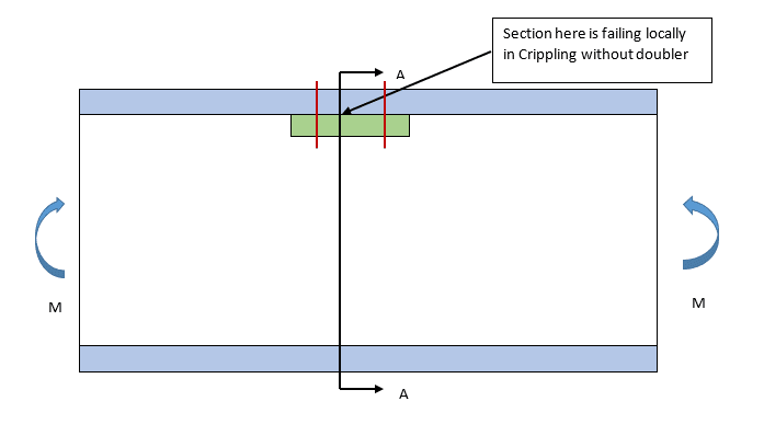
Have a beam with C-channel cross-section subjected to Bending Moment as shown below. Let’s say that at Section A-A, the beam is failing locally in Crippling. Question is to find ways of mitigating failure of component in Crippling.

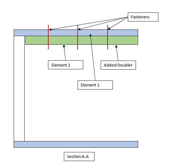
One of the ways I can think of is to increase the size of cross-section. Since increasing the geometry size globally would be uneconomical from weight point, locally reinforcing the region with a doubler of same material & thickness attached to the upper flange using fasteners is one possible design solution I can think of!

Does the above even work? That is, do the doubler & flange act in unison to resist Crippling load?

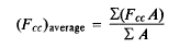
During of calculation of Crippling load for revised geometry using Needham’s Method, how can the width & thickness of the doubler be incorporated with the original beam flange? Should I calculate the Crippling Load for Element 1 & 2 separately and use the below formula for calc crippling load for both members?

01_p7kpfw.png


The other option to mitigate failure is to go for a stiffer material (higher Ec) in that region, but not sure how practical it would be from a design POV.

Would appreciate suggestions on how to handle the above.

A couple of images to illustrate the above issue. The fasteners used are for illustration purposes only.

02_oyn5ze.png


03_wvngmm.png
 
Replies continue below

Recommended for you

Hi VN1981,

Since the crippling allowable is a function of the b/t ratio of the element, you might be able to get some benefit there. If your b/t is too high, you will have a low crippling allowable. For one edge free, try to keep b/t less than about 10, for no edge free, try to keep it less than about 30. So, if your current design has too high b/t, you can increase the allowable by revising the dimensions to get a lower b/t (decrease the width and/or increase the thickness). If you are already using a reasonable b/t, then you have no choice but to increase the area of the element. Since the maximum Fcc is usually cut-off to something like Fcy, you can make a quick estimate of how much area you need by using Fcy as your allowable first. If your current sizing is not even close with using Fcy as your allowable, then you have to increase the area. That is what "sizing" is all about!

However, how are you getting the load in the element? From your drawing, it looks like the compression load is being shared between both the skin (blue) and flange (green). If so, by changing the area of the flange, it will also pick up more load. The load split between the flange & skin depends on the EA ratio. Or, are you are saying that the flange has to take the entire compression load? Exactly what your design concept is makes a difference on how you should analyze it.

If the skin is thin and you are allowing it to buckle, then the usual approach is to compute the crippling load of the stiffener (flange) alone, and then compute what the effective width of the skin is at that stress level. Then the combined flange area along with the effective skin area is the area you use to carry the load. If that is not enough, you have to increase the amount of material - again that is "sizing" and might take a few iterations.

Most likely, the material choice is set by other considerations for the overall design. Although theoretically a material with a higher E and/or a higher Fcy would have a higher crippling stress, it would probably not be an option to change the material based only on the need to satisfy crippling at one location.

 
Using lipped doublers would certainly be better than plan flat doublers. I would possibly have lips on both edges. The doublers would then need checking for inter-rivet buckling although as stability is the critical mode I would be reluctant to use countersink rivets on this.

If this is a standard extrusion section, I would look closely for obscure compression stability failure modes as typically someone spent a bit of time optimizing the shape.
 
Hi sdm919,
Thanks for your reply.

The blue elements represents the Flanges of the C-Channel beam and Green element represents the doubler which will be attached to the flange using fasteners. I am aware of the concept of Skin Effective Width, but I fail to see how it will be applicable to the above case.

Thanks for the tips on Crippling load optimized b/t ratios for different edge free conditions. Will be a helpful pointer in future.

verymadmac, good suggestion on using lips. Somehow did not cross my mind. Yes, inter-rivet buckling would need to be checked as well.

 
Good points by sdm and Mac. However, if you do plan to use a doubler you need to bend the doubler to pick up a row of fasteners in the shear web. The doubler should reinforce the beam where moments cause the original section to fail in crippling (your FBD shows constant moment so the doubler would have to span the full beam length). Further, you should probably use .75 * total thickness rather than adding the thicknesses (Ref Bruhn, Section C7.12). Hope this helps.
 
For the load share, an EA split would be valid if it were bonded. However, since it is mechanically fastened, you should consider a hard point analysis instead. Fasteners are a much softer load path than bonded joints so the doubler will pick up less load than the EA split predicts. Regardless, you need to establish how much load is in the doubler and how much is in the flange.

Then update your flange calculations with the lower loads (double will pick up some of the load). Then analyze the doubler with however much load goes into it and also be aware that the doubler stability is a function of how you integrate it into the beam (lips, no lips, tied into the web, other). The analysis will help guide you as to the design requirements.

Brian
 
Folks,
Firstly, thank y'all for the replies.

Perhaps people missed it, but the scenario I've presented is hypothetical. I realize the FBD shows a constant moment acting on the beam. Actually, the question was posed during a telephonic interview.

Question was, what ways would you mitigate if there is failure from Crippling in a beam. Perhaps, I should have sought more details/clarity but my first thoughts were to increase the dimensions locally by using a doubler. Adding a lip perhaps is a better option (not sure how I can add a lip to an existing structure).

I just expanded the above question/scenario by introducing a hypothetical beam along with a scenario of end moments to give some clarity (may be not needed) in my original post.

Again, thanks for the contribution. Gaining some additional insights.

 
Status
Not open for further replies.
Back
Top