VN1981
Aerospace
- Sep 29, 2015
- 186
Hello,
A Hypothetical Question:
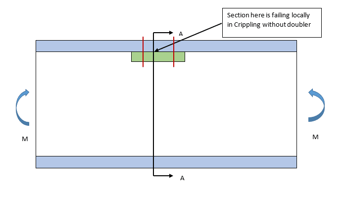
Have a beam with C-channel cross-section subjected to Bending Moment as shown below. Let’s say that at Section A-A, the beam is failing locally in Crippling. Question is to find ways of mitigating failure of component in Crippling.
One of the ways I can think of is to increase the size of cross-section. Since increasing the geometry size globally would be uneconomical from weight point, locally reinforcing the region with a doubler of same material & thickness attached to the upper flange using fasteners is one possible design solution I can think of!
Does the above even work? That is, do the doubler & flange act in unison to resist Crippling load?
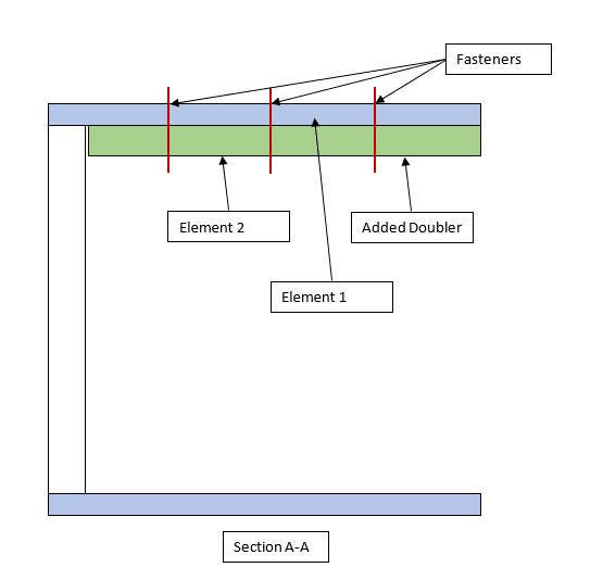
During of calculation of Crippling load for revised geometry using Needham’s Method, how can the width & thickness of the doubler be incorporated with the original beam flange? Should I calculate the Crippling Load for Element 1 & 2 separately and use the below formula for calc crippling load for both members?

The other option to mitigate failure is to go for a stiffer material (higher Ec) in that region, but not sure how practical it would be from a design POV.
Would appreciate suggestions on how to handle the above.
A couple of images to illustrate the above issue. The fasteners used are for illustration purposes only.


A Hypothetical Question:
Have a beam with C-channel cross-section subjected to Bending Moment as shown below. Let’s say that at Section A-A, the beam is failing locally in Crippling. Question is to find ways of mitigating failure of component in Crippling.
One of the ways I can think of is to increase the size of cross-section. Since increasing the geometry size globally would be uneconomical from weight point, locally reinforcing the region with a doubler of same material & thickness attached to the upper flange using fasteners is one possible design solution I can think of!
Does the above even work? That is, do the doubler & flange act in unison to resist Crippling load?
During of calculation of Crippling load for revised geometry using Needham’s Method, how can the width & thickness of the doubler be incorporated with the original beam flange? Should I calculate the Crippling Load for Element 1 & 2 separately and use the below formula for calc crippling load for both members?

The other option to mitigate failure is to go for a stiffer material (higher Ec) in that region, but not sure how practical it would be from a design POV.
Would appreciate suggestions on how to handle the above.
A couple of images to illustrate the above issue. The fasteners used are for illustration purposes only.


