Eng-Tips is the largest engineering community on the Internet

Intelligent Work Forums for Engineering Professionals

Cross Bracing Configuration in Wall with Windows 1

Status
Not open for further replies.

EV11

Structural
Mar 30, 2021
10
0
0
CA
Hi Everyone,
I am an engineer in training and I have a quick question regarding lateral bracing for structural steel buildings.

I am currently working on the design of a standard one-storey structural steel building (square geometry, retail store). The front wall of the building is almost entirely made up of windows. In this wall, I need to include a type of bracing to resist lateral wind loading however, the architect + client prefer not to have bracing members exposed in the windows.

I would be able to add in cross bracing (or X bracing) in the upper section of one of the frames (as there are no windows here) – see attached sketch. Note that this is a one-storey building, the beam shown at mid-span of the frame in the sketch is a horizontal strut that will also be used to support a small entrance canopy.

My question – is this bracing configuration acceptable? I am concerned about load path. It has always been my understanding that braced frames (single or multi-storey) must be designed so that the lateral load can travel through the bracing members and make its way to the foundation. I might be overthinking things, but my configuration does not appear to allow that.

I know that incorporating a moment frame would be an option, but I would like to stick with bracing if possible.

Thank you.
 
 https://files.engineering.com/getfile.aspx?folder=6ecafcc6-d3c1-49a6-85d5-cca43f8c326a&file=Cross-Bracing_Configuration.pdf
Replies continue below

Recommended for you

Ev11, have you looked at providing bracing on the sides and rear of the retail store? ie a 3-sided box. This could be an option and you just need to check that the additional twist from an eccentric wind won't deform the front glazed side enough to damage the glass.

If you need a bit more bracing stiffness on the front glazed wall, you could go with what you've shown in your sketch. Essentially you're bridging the gap between the bottom of the diagonal bracing and the foundation via bending within the SHS columns. You then get a push/pull in the lower portions of the columns too. If you do up a quick analysis model you'll see this behaviour.

Keep in mind, if the X-bracing are either rods or flats, then you'll need to run second order analysis and set those members to tension-only.
 
As Trenno suggested, I'd start with a three sided LFRS and see if it gives you favorable results. If it doesn't, then this is a viable solution. This is essentially a moment frame as long as the columns are continuous from the foundation to the diaphragm connection.
 
EV11 said:
I know that incorporating a moment frame would be an option, but I would like to stick with bracing if possible.

As noted by phamENG, you already are essentially creating a moment frame. The columns are acting as bending between the bottom beam of your cross bracing and the ground. The cross bracing essentially acts as a very deep beam in a moment frame. As said by the others, I would look and see if a three sided lateral system works.
 
Many engineers, including me, will be of the opinion that you ought to include your moment frame even if you do the three sided building thing. More so if this is in a high seismic region (not in most areas of Ontario). The three sided building business is a legit technique in terms of equilibrium but it asks a lot of:

1) the diaphragm
2) the diaphragm fastening
3) the diaphragm boundary elements
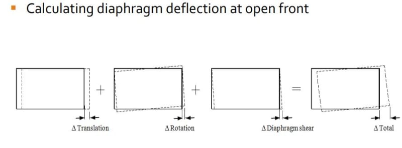
4) your diaphragm analysis accurately capturing displacement at the open side of the building and the impact that will have on the global, P-Delta demand generated by your gravity columns moving through that displacement.

Anecdotally, these things have a disproportionate habit of racking over during serious seismic events.

Lastly, unless I miss my mark, your diaphragm aspect ratio is likely not favorable for this (1:1-sih). Depending on the deck material, seismicity, and governing code, an aspect ratio like this will often either be disallowed or punished as an extreme torsional irregularity.

If your frame will be expected to exhibit ductility under seismic load, the arrangement that you show would almost certainly force the plastic hinging into the columns rather than the beams since, as others have said, the upper tier is effectively a giant beam. I'd argue that this lack of strong column - weak beam behavior would actually be alright in this situation since the frame is effectively a single story element despite the two tiers.

OP said:
My question – is this bracing configuration acceptable?

In short, yeah, it would be acceptable. As far as moment frames goes, it would be wickedly stiff which is great. Almost as though your columns were fixed rotationally a little above the low beam.

c02_di6j6i.jpg
 
I have done this configuration many times. It forms a portal, and works fine. Don't skimp on column size, and don't assume base fixity (unless you're VERY sure).

As a reference we did one that was 8m tall total, 11m column spacing, with 3m braced section (5m unbraced section). 250UC columns. It was borderline and there were some complaints during construction because the roofers could feel some sway.

Like the others I recommend bracing the roof back to full depth bracing bay (e.g. the three sided suggestions by others). If you brace the roof directly to ground it's much stiffer.

 
Tomfh said:
Like the others I recommend bracing the roof back to full depth bracing bay (e.g. the three sided suggestions by others).

Is it correct to assume that, in your world, the bracing mentioned in bolded font above would actually be true diaphragm bracing in the sense that it is:

1) Discrete horizontal bracing using rods, cables, angles etc and;

2) Not just a bare steel deck diaphragm performing the bracing function without discrete bracing as is common in North America?

That is my understanding of AU practice based on the Aussie traffic that I've seen here. I like three sided buildings a whole lot better when the diaphragms are discretely braced.
 
Yes Kootk the horizontal bracing system is invariably rods/struts/rafters. The sheeting is generally considered a bonus, even though in reality it probably does the grunt work.
 
Can the ends of the front wall have wall area? or does the full elevation have glazing... I've done it with three sided bracing as well as a portal system... pinned at the base as Tom notes, but connected for full design moment assuming it was fixed... just to stiffen it with all the glass.

Rather than think climate change and the corona virus as science, think of it as the wrath of God. Feel any better?

-Dik
 
What you propose, with bracing above the opening, gives you a moment frame. You just have to analyze it to ensure it is stiff enough, which may require boosting up the column size. I am not a proponent of 3 sided boxes for resisting lateral forces.
 
How long (wide) is the run of windows that the client wants as a clear opening?

the classic solution is to add posts, coordinated to line up where the window mullions land
 
If this is anything like the countless strip malls we've done, there is next to no wall left along the front. Maybe 1 or 2 feet to hide the columns and provide somewhere to mount the outside wall sconce lighting, otherwise glazing as far as you can see.

We have done the portal frame method all of the time in these structures. Could it work as a 3 sided box? Sure. But you end up needing the low beam (girt) regardless at the top of the glazing, may as well throw some bracing in above it and stiffen everything. Helps you sleep better at night.
 
The likely need to have a frame regardless of the lateral situation is a fine point jayrod12. These frames are kind of "Easy Bake Moment Frames". You reduce field erection costs by eliminating the beam to column moment connections and only pay a premium in terms of steel weight (mostly the columns, maybe a little on the beams). Additionally, it has been my experience that front to back drainage dictates that these setups will often have meaningful dead load applied to them to help resist overturning. It almost seems a shame to not exploit the frames in this way.
 
Status
Not open for further replies.
Back
Top