Continue to Site

Eng-Tips is the largest engineering community on the Internet

Intelligent Work Forums for Engineering Professionals

  • Congratulations SDETERS on being selected by the Eng-Tips community for having the most helpful posts in the forums last week. Way to Go!

CSA S16-14 Maximum Slenderness of Angle Legs

Status
Not open for further replies.

Baffled Engineer

Structural
Jul 27, 2018
57
What is the correct limitation on slenderness of legs of angles for a double angle compression chord of a girder truss?
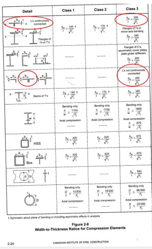
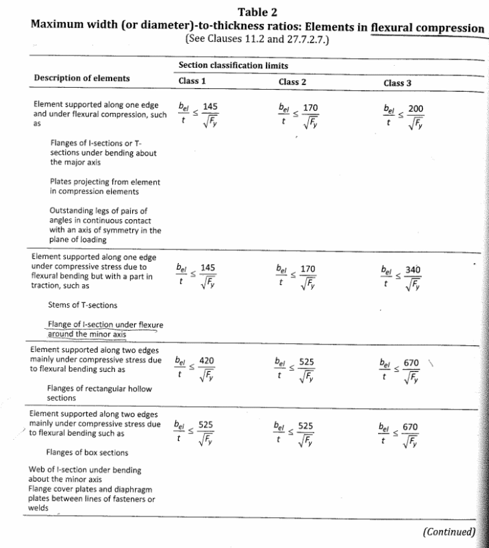
I have attached the relevant tables below.

The angles are primarily resisting compressive forces but there are some minor flexural stresses as well.

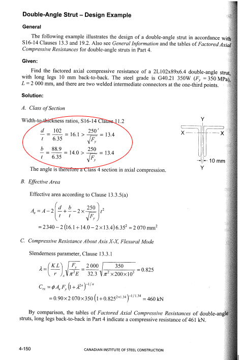
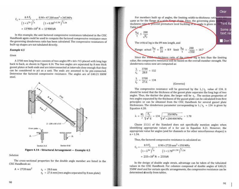
My confusion stems from the fact that under pure axial compression, table 1 allows a slenderness of 250/sqrt(Fy), but under flexural compression, Table 2 allows for a more stringent slenderness limit of 200/sqrt(Fy). Intuitively, I would think an angle leg under full compression is more critical than a leg under flexural compression so it doesn't make sense why the slenderness is more critical under flexural compression.

The existing angles that I'm working on are 2L6x4x1/2 LLBB and 2L7x4x1/2 SLBB with an Fy of 300mPa, and the slenderness I have are between 200/sqrt(Fy) and 250/sqrt(Fy)... which would make them class 4 if the correct slenderness limit is 200/sqrt(Fy).

I appreciate the help guys. Thanks.
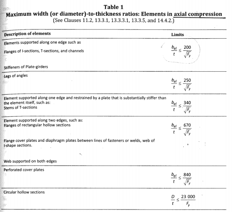

Table_1_mcctuu.png

Table_2_d7ijbc.png
 
Replies continue below

Recommended for you

I have two examples that contradict each other. The first one is from the steel handbook (2016), and the second one is from the CISC Limit States Design in Structural Steel by Kulak & Grondin (10th edition - 2016).

ex_1_ewyec8.png

ex_2_tgwqbm.png
 
Hi there,
Compression cord in a girder truss is subjected to bending and deflection so I suggest to use the slenderness ratio from flexural compression table,
cheers we are in this together
 
I would guess that as long as you meet the requirement of the CISC clauses for angles in compression you can apply the less stringent compression limit, although in S16-09 it has 200 and not 250 for angles in compression, so I'd personally stick to that. Is there a correction published for S16-14 or was this intentional? Best to ask them.
 
Satya91 said:
Hi there,
Compression cord in a girder truss is subjected to bending and deflection so I suggest to use the slenderness ratio from flexural compression table,
cheers we are in this together


Satya91,

Would you know why the flexural compression slenderness limit is more severe than the full compression element limit?

The girder truss is mainly loaded on the panel points and the moment is very small even with P-Delta effects. So we're looking at about 1000kN axial force and about 5knM moments...I suppose the correct way is to calculate the axial capacity according to the slenderness in Table 1, and the moment capacity based on the slenderness limit on Table 2. I don't think it's correct to use the same slenderness limit in determining both the axial and flexural capacity.

Regards,
 
Pure axial compression for the angle assumes no eccentricity, so your angle leg can get bigger.
Flexural compression assumes there are other stresses, so it limits the leg size.

For what it is worth, CSA S37-18 (antenna support structures) uses 210/SQRT(Fy) but classifies the leg as the effective leg width (basically leg - thickness). And then gives you two inequalities to reduce the Fy to meet the Class limits.
 
canwesteng said:
I would guess that as long as you meet the requirement of the CISC clauses for angles in compression you can apply the less stringent compression limit, although in S16-09 it has 200 and not 250 for angles in compression, so I'd personally stick to that. Is there a correction published for S16-14 or was this intentional? Best to ask them.


Canwesteng,

It's new to S16-14...but this additional limitation specifically for angles has been in S16-14 for 6 years already and there has been no correction / errata. I would assume CISC has a good reason why they relaxed the slenderness requirement, and I would like to take advantage of this unless it's actually incorrect...
 
skeletron said:
Pure axial compression for the angle assumes no eccentricity, so your angle leg can get bigger.
Flexural compression assumes there are other stresses, so it limits the leg size.

For what it is worth, CSA S37-18 (antenna support structures) uses 210/SQRT(Fy) but classifies the leg as the effective leg width (basically leg - thickness). And then gives you two inequalities to reduce the Fy to meet the Class limits.


Skeletron,

Thanks. I think your explanation makes sense about the added eccentricity on the element...but in the commentary at the back of the steel handbook they make a distinction between double angles continuously connected and double angles separated from each other say by filler plates (which is the case for the girder trusses I'm working on). So I think the reason has something to do with the connectivity between the angles...I'm just not sure why.


slenderness_kuqeky.png
 
The slenderness limits help distinguish the classification of the section and the controlling buckling mode (flexural, torsional, flexural-torsional). This then defines the critical stress. AISC uses a Q factor to de-lineate between three critical stress equations whereas CISC has chosen to bi-sect the curve.

Not sure I can satisfy your curiosity and answer your question, but that is the "just" I got from reading McNulty's Single Angle Design Manual.

In the "not continuously connected case" I would tend to think that the angles may be buckling in the torsional/flex-torsional mode and so the slenderness limit is increased with the added caveat that the angle should satisfy the criteria which deals with these failure modes.

The top 200 limit is hard and fast for non-compact sections which fail in the flexural mode.
 
Status
Not open for further replies.

Part and Inventory Search

Sponsor