Continue to Site

Eng-Tips is the largest engineering community on the Internet

Intelligent Work Forums for Engineering Professionals

  • Congratulations IDS on being selected by the Eng-Tips community for having the most helpful posts in the forums last week. Way to Go!

CSTATUS to make sure contact between three cylindrical parts is accurate? 1

Status
Not open for further replies.

drennon236

Civil/Environmental
Mar 27, 2020
102
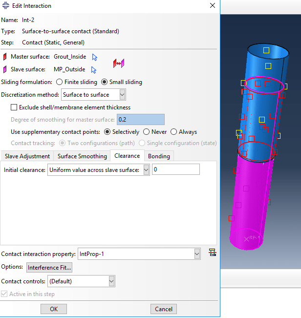
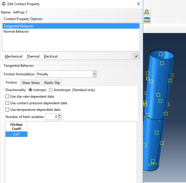
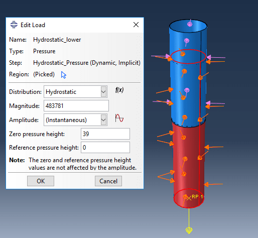
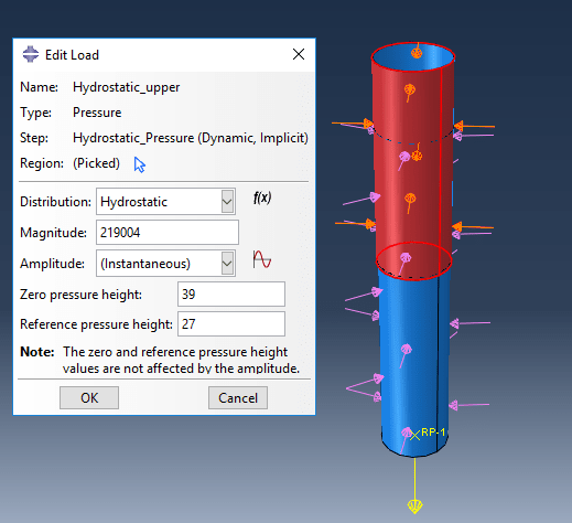
I have 2 steel cylindrical parts, and in the middle is a cylindrical part (concrete - grout). The concrete part is supposed to stop any movement between the parts simply through friction. Below the interaction properties are shown:
Interaction between concrete (grout) and upper steel part and lower steel part:
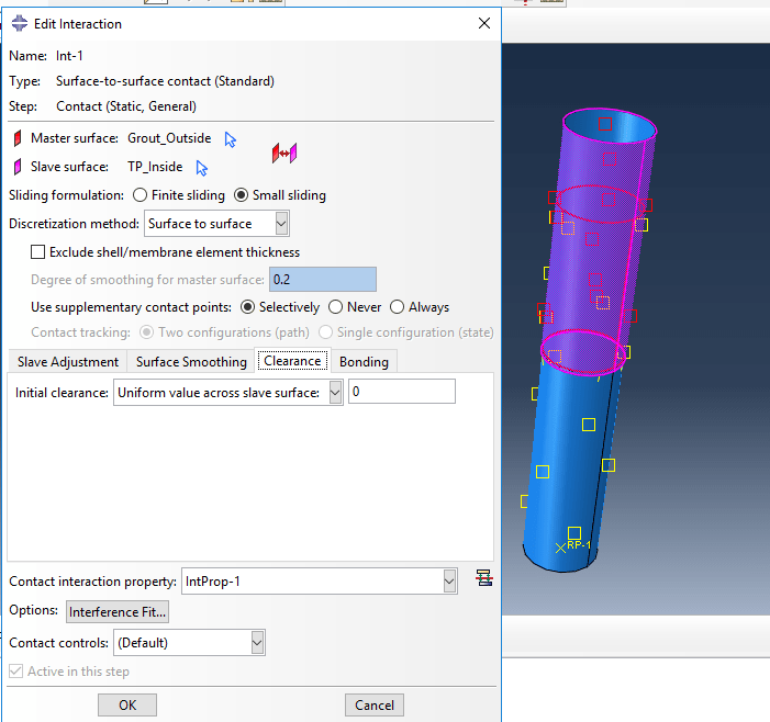
Capture_c4tzgv.png

Capture1_zcu8mk.png

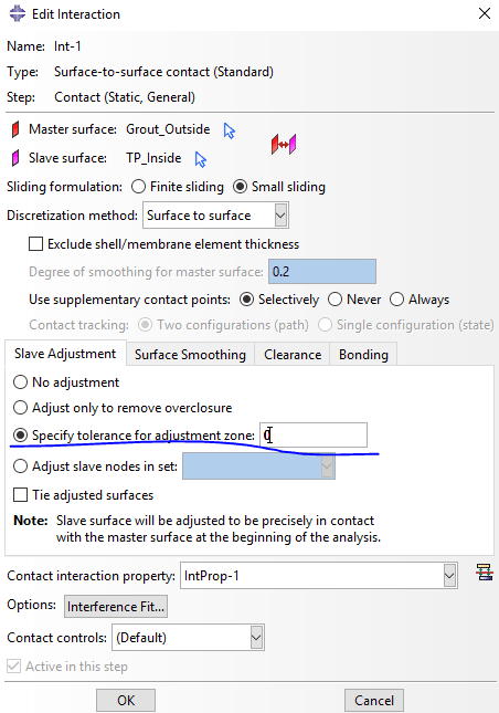
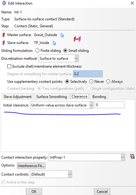
Interaction properties:
Capture2_ixsr1i.png

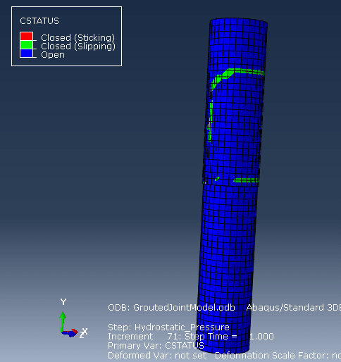
CSTATUS:
Capture3_b3ioon.png


Pretty much all nodes seem to be open, I tried to fix this by setting sliding formulation to "small sliding" and uniform value across slave surface to zero. Shouldn't all nodes be closed? Or atleast sliding? Is there something I am misunderstanding, and how can I fix this? I know a finer mesh helps with this, but the improvement was minimal when I tried.
 
Replies continue below

Recommended for you

Are these shell or solid parts ? How is the model loaded ? You may have to use the slave adjustment feature.
 
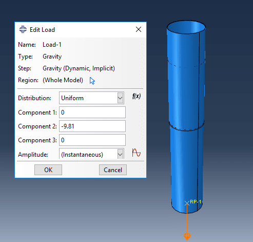
Its all solid C3D8R elements, I am applying self weight and hydrostatic pressure. The first step (after initial), is to make contact. Then I apply self-weight, and finally hydrostatic pressure.
Capture_lzcuko.png
Capture1_l5b3a5.png
Capture2_ultqnp.png

Any specific thing I should look into for slave adjustment?
 
Yes, adjustment tolerance is very important. Deafult value of this parameter may not be enough. In such case you can specify it manually. It should be approximately equal to the distance between surfaces (be careful here not to use too large value or it will move more nodes than necessary).

Keep in mind that this is strain-free adjustment. If you want to include the strain resulting from adjustment in results, use interference fit.
 
So as I understand it, I have to adjust this parameter to be the distance between surfaces (which I believe is 0, so that there is no gap between the parts):
Capture1_vuupkc.png

As this is not enough to cause zero gap between parts:
Capture3_wbncyr.png

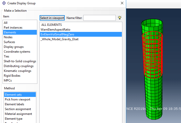
When I try to run the inp file, I get the error "The volume of 140 elements is zero, small, or negative. Check coordinates or node numbering, or modify the mesh seed. In the case of a tetrahedron this error may indicate that all nodes are located very nearly in a plane. The elements have been identified in element set ErrElemVolSmallNegZero."
Capture_wropmx.png

So as I understand it I need to refine my mesh at the point where this error occurs - I was thinking of having a finer mesh at the contact surfaces? Is this worth trying out, have a rough mesh, but fine where contact occurs. I still would like to keep element type C3D8R, but if I were to change what would be worth trying?
 
This tolerance value is the maximum distance from master surface at which Abaqus searches for slave nodes (and adjusts those that were found so that they are in contact with master surface). Small/negative/zero volume error in this case means that Abaqus found nodes that shouldn't be adjusted because their adjustment results in high distortion of corresponding elements.

These parts are very thin, I would definitely use shell elements.
 
I was thinking of shell elements aswell, but it is recommended using brick shaped 3D continuum elements to the largest extent possible:

Bank_o2b5qa.png


I also need to model what is referred to as "shear keys" in the paper, meaning I cannot proceed with shell elements. If the extra fine mesh at contact surfaces isn't enough to fix the problem, is there anything else I could look into?
 
Make sure there’s no overclosure between the contacting parts (it seems that there might be some overclosure in your model). It should be possible to adapt the adjustment in such way that it works correctly.
 
Thank you FEA way, just last questions for today;

- How do I go about fixing the overclosure problem? (Just where to start)
- Do you think it would work to have finer mesh where parts connect?
- Should I mainly focus on the slave adjustments?
 
In case of overclosures you can use the option named "Adjust only to remove overclosure". It can be found in the same place as adjustment tolerance setting.

Refined mesh should help but most likely it won’t be sufficient.

Right, if there are no overclusures, focus on adjustment tolerance.
 
Ah okay, I did try the "Adjust only to remove overclosure" and still got the same error. I will keep trying, thank you for the help.
 
Status
Not open for further replies.

Part and Inventory Search

Sponsor