Eng-Tips is the largest engineering community on the Internet

Intelligent Work Forums for Engineering Professionals

  • Congratulations waross on being selected by the Tek-Tips community for having the most helpful posts in the forums last week. Way to Go!

CT secondary wye point grounding 2

Status
Not open for further replies.

NickParker

Electrical
Sep 1, 2017
396
0
16
NL
For differential protection, I can see the CT secondary wye point grounding on both sides.

Differential_protection_iugap5.png


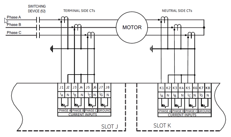
Although some of my coworkers claim that this also works flawlessly, I am aware that doing so goes against IEEE Std C57.13.3-2014 - IEEE Guide for Grounding of Instrument Transformer Secondary Circuits and Cases.

Any thoughts!
 
Replies continue below

Recommended for you

The phase side and neutral side CT secondary wires are brought to the differential relay. The neutral to be earthed at the relay so that multiple earthing is avoided.
There are many instances where multiple earthing has caused maloperation of differential protection (when the two earths are in different panels).
 
Both sets of CTs "should" be arranged so that they point in opposite directions, the convention being that that they both point toward the motor. But many relays now allow a "backward" CT to be flipped in the relay logic rather than physically in the field. I don't recognize that diagram so I don't know what type of relay or what its capabilities are.

I’ll see your silver lining and raise you two black clouds. - Protection Operations
 
Diagram appears to be copied right from a Multilin or SEL manual and they wouldn't draw the wrong way to install CTs in their manuals. So, what is the problem.
 
LionelHutz said:
Diagram appears to be copied right from a Multilin or SEL manual and they wouldn't draw the wrong way to install CTs in their manuals. So, what is the problem.

Yes, even the ABB manual shows the same wiring; nonetheless, why is it in violation of IEEE guidelines?
 
Differential relays work by summing the currents. Unless the relay inverts one set of currents as David said, normal motor load will cause differential current and a likely trip. Check those manuals again.

The grounding is a safety issue. With two grounds coming from different directions plus a case ground on the relay, you have three different source of ground potential. Best to have just one.
 
Dear Mr. NickParker (Electrical)(OP)20 Dec 22 15:39
"#1... For differential protection, I can see the CT secondary wye point grounding on both sides......even the ABB manual shows the same wiring.... "[/color]
1. It is WRONG that the CT secondary wye point grounding on both sides.

1.1 Remove those two ground points.
1.2 Very often, drawings in the catalogue go to the printer without going through deliberative "technical" vetting! Caveat emptor.

" #2..... some of my coworkers claim that this also works flawlessly, I am aware that doing so goes against IEEE Std C57.13.3-2014 - IEEE Guide for Grounding of Instrument Transformer Secondary Circuits and Cases; "
2. Your coworkers are ILLINFORMED. Correct/educate them.
2.1 IEEE Std C57.13.3-2014 is CORRECT. comply with it.

3. The CT dot notation and the terminal points for symmetry reasons could? by correct. They may? had it that way; but had inverted? it internally.
3.1 Attention: (i) The terminal N in slot J and K may? NOT be grounded internally. Check to reconfirm. (ii) if Ns are not grounded internally, connect Ns in slot J and slot K ; then ground them at one and only one point.
Che Kuan Yau (Singapore)


Normally the diff CTs has to be grounded only at one place. That means at the relay panel inside the building.
In case if the two grounds are at two different potentials during a ground fault, depending on the pickup value,
the relay might work due to spurious GF currents.
 
The relay doesn't have grounded terminals, otherwise they wouldn't show separate grounding for the CTs. That relay in the picture will have 2 completely different and isolated CT input circuits, it could even be the exact same input card stuck into 2 different option slots of the relay. So, in the illustration, every CT is only grounded one time.

Do check the manual, it might specify to ground the CT's in the relay cabinet as opposed to say at the motor.

Digital relays can do math, and sum CT values the correct way internally.
 
Just to add a comment, the font looks like what GE Multilin uses - so I can give an example from the SR745 from that vendor - it might be relevant here.

If you connected early versions of the SR745 using IEEE conventions, it would trip incorrectly for an external fault. The REF input had a different polarity to the other AC inputs.

They fixed it up for a while by showing the side of the CT pointing towards the transformer into the polarity input of the relay in the manuals (i.e. ignore the convention) - but this was papering over the actual problem.

They later fixed this up in the firmware and changed the connection diagrams in the manual, meaning if you replace an old relay with a new one the wiring connections need changing.

Further, the problem was actually not the REF input (it was correct). All sinewaves in the SR745 go the opposite way to what all other relays do.

But if everything is wrong, then it all corrects itself and it won't trip (which is what happens in that relay)

What Lionel says is worth noting, the manual may be correct even though it goes against IEEE conventions - but to add something further make sure your manual matches your firmware version.

And above all else - test it properly. This is one of the reasons testing is so important.
 
Status
Not open for further replies.
Back
Top