Continue to Site

Eng-Tips is the largest engineering community on the Internet

Intelligent Work Forums for Engineering Professionals

  • Congratulations IDS on being selected by the Eng-Tips community for having the most helpful posts in the forums last week. Way to Go!

CT Wiring Question

Status
Not open for further replies.

mbk2k3

Electrical
Nov 18, 2010
97
Hi folks!

I'm very curious about how modern multifunction relays handle the connection of CTs. Especially when it comes to power flow.

Will the CT wiring look any different If I have a 4.16kV feeder that is connected to a medium voltage motor instead of a medium voltage generator?

I have a 4.16kV generator feeder and at first glance of the CTs, it seems like it will give me negative power readings at the Multilin G30 protection relay.

See attached PDF for a better idea of what I'm talking about.

 
 http://files.engineering.com/getfile.aspx?folder=d040bde8-59d1-4f7d-9aa4-a6859ed8eebf&file=Question_for_GE.pdf
Replies continue below

Recommended for you

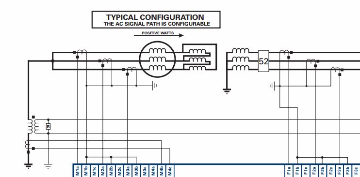
The G30 is a generator PR. I would highly recommend that you follow the convention supplied in the OEM manual per thee following;
2017-03-27_14-20-01_rzrwtf.gif

Most modern relays will permit you to adjust for any differences in the recommended wiring method, and what was actually installed. For example the above three-line diagram shows a step up transformer, which you may , or may not have. There will be configuration settings somewhere in the relay to accommodate this.
This relay will have a whole bunch of phase sensitive settings (including 32, 87, 67, etc). ie Always best to follow the OEM's recommended wiring methodology.

BTW, how large is the machine? You might be better off with a GE-489 relay (which is better suited for smaller machines). It is also less expensive.


"I have not failed. I've just found 10,000 ways that won't work." Thomas Alva Edison (1847-1931)
 
I agree that using a generator relay to protect a motor seems a little strange, especially considering that GE-Multilin have such a good range of dedicated motor protection relays. Is there a reason why you've chosen an expensive generator relay over a motor relay? The mid-range G30 is about the same price as a top-of-the-range M60 relay.
 
sorry i should have been clearer.

i'm not using a generator protection relay to protect a motor or anything like that.

i'm just curious what would be different in terms of hardware/wiring between:

a) 4.16kV switchgear with three feeder breakers connected to generators
vs.
b) 4.16kV switchgear with three feeder breakers connected to motors

i.e. would CTs have to be wired differently due to power flow direction in opposite direction? or can modern relays compensate for that?
 
Hi mbk,
As the 3-line attached above states "The AC Signal Path is Configurable" . I am confident that this will be the case with most PRs that are phase (& phase-rotation) sensitive.
Regards,
GG


"I have not failed. I've just found 10,000 ways that won't work." Thomas Alva Edison (1847-1931)

 
To measure power, you need voltage as well; and no VTs are shown in your diagram. Power direction depends on the polarity of both the CTs and VTs. Most protections don't care, it would be the metering functions in the relay that are affected. In the SEL family of products, the setting is called COMPANG. Don't know if GE has an equivalent.
 
Hey Steve,
The GE-30 3-line shown above, is only a partial, and does not show the VTs. Obviously a generator PR will have at least one set of PT inputs, more if the PR has (25) synch-check capabilities. The OP was only concerned with CTs.
Regards,
GG

ps For you purists, here is the entire 3-line diagram;

2017-03-28_8-56-20_wf28xi.gif


"I have not failed. I've just found 10,000 ways that won't work." Thomas Alva Edison (1847-1931)
 
What does "AC path is configurable" mean? That you can adjust via settings which direction the powerflow is in?

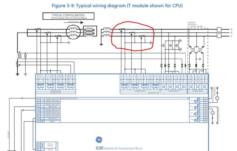
Thanks for the schematic GroovyGuy, but I've seen several versions of that schematic. In the latest one off the GE website it looks different. See below.

In the sketch you attached, the neutrals on the generator side were tied together and grounded.
In the sketch below, the neutrals on the utility side are tied together and grounded.
Do both methods work?

Capture_hy84zg.jpg
 
It's the same CT secondary wiring, the CT's are just shown installed in the opposite direction.
 
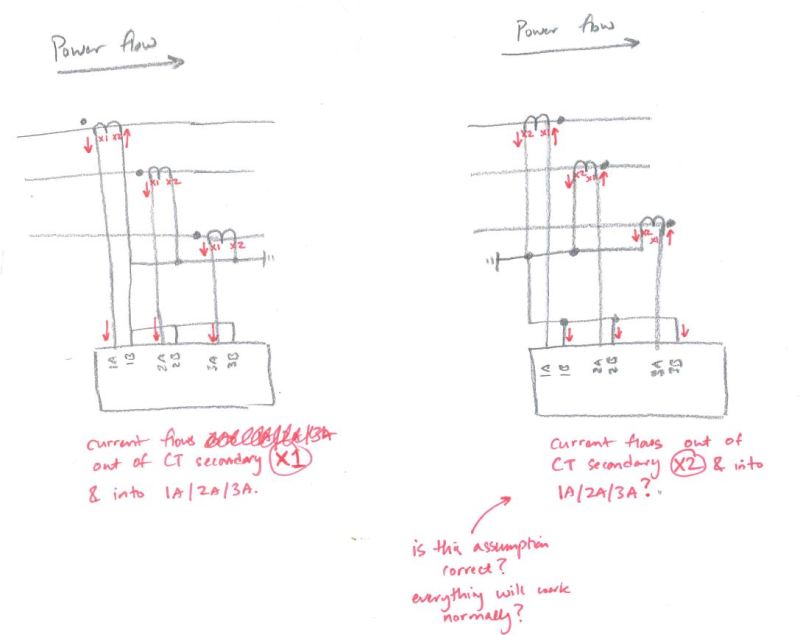
is my understanding of the secondary current flows correct (see sketch below)....
isn't the secondary current flow reversed? or does the G30 relay (and similar relays) have a setting that allows you to compensate for this?

Capture2_efo8co.jpg
 
Assuming the VTs are connected as shown further above, you want the current to flow into the polarity current input on the relay during the positive half cycle. It looks like yours is going into the non-polarity (marked B, confusing notation). Rewire the right drawing so X2 goes into the polarity (A) and you have it. We will generally wire it so X1 becomes the common.


Hi Steven,

Thats not my notation, thats how GE has it wired up in the manual i attached (see screenshots above).

 
Now I remember why I don't like GE.
Since your relay apparently provides differential protection, and works across a delta/wye transformer as shown; it will have a method of compensating for various shifts. How it meters, though, may be different story.
 
Hi mkb,
Please review to the Settings/System-Setup tab in the G30 manual. I believe that you will find your explanation buried somewhere in the manual. Through the config settings for the relay you can pretty much accommodate any CT/VT arrangement.
GG


"I have not failed. I've just found 10,000 ways that won't work." Thomas Alva Edison (1847-1931)
 
See 6.3.1. This would be where I would expect to see a quadrant shift setting for metering. I don't see one.
 
Status
Not open for further replies.

Part and Inventory Search

Sponsor