Continue to Site

Eng-Tips is the largest engineering community on the Internet

Intelligent Work Forums for Engineering Professionals

  • Congratulations MintJulep on being selected by the Eng-Tips community for having the most helpful posts in the forums last week. Way to Go!

Current sharing in parallel circuits 5

Status
Not open for further replies.

lennythegent

Electrical
Feb 22, 2017
4
hi I'm new so go easy!

we have installation of 9 (3 x r-y-b trefoil groups) and current sharing between phases is imbalanced greater than 10%. Could the physical arrangement/layout of cables be cause (or contribution) to this imbalance.

The lay is trefoil as mentioned, but the route is not consistent, in some places all three trefoil bundles are touching, in other parts equally spaced, and other cases where the cable run has two trefoil groups touching and one group is spaced.

i've browsed net a bit and found couple of discussion on this site and also a found this commentary that mentions with 9 cables there is no perfect arrangement and 5% imbalance could be expected (even if spaced)
the fact our installation doesn't have consistent spacing could this be cause for imbalance.

i've also read iec 60287 has more info but I don't have access to this at moment and would like to probe the thinking first before purchase.

I realize there could be other reasons for imbalance but I would like discussion to concentrate on this particular question if possible, thanks
 
Replies continue below

Recommended for you

I don't know about cables. I have seen the currents on a ring bus split very weirdly. On bus work or maybe even short cables, the connection impedance might play a bigger role in creating imbalance than the inductance for that length of cable or bus.
 
I am not sure if purchasing the standard will help you answer your question.
Without know the details such as a few representative cable section arrangement , length, type of cable, voltage, etc.
The first impression is that a trefoil configuration with the parallel cable tie at the sending and receiving ends may not be the cause of 5% of voltage imbalance.
We suggest to measure both ends voltage of the feeder cable to determine if this is the case of imbalance.
 
In a very low impedance loop circuit exceedingly small differences in impedance one way vs. the other way around the loop can result in significantly large imbalances in current splits.
 
If the cables are touching and the configuration is r-y-b b-y-r b-r-y then unbalance could be 11.8% See:
A CABLE CONFIGURATION TECHNIQUE FOR THE BALANCE OF CURRENT DISTRIBUTION IN PARALLEL CABLES
IS_1 configuration.
Table 2. Results for a 3φ3W 9-cable system with structure
3_PARALLEL_CABLES_CURRENT_UNBALANCE_gb8har.jpg
 
thanks for response, especially paper provided by 7anoter4. As usual theory never matches practice and our install differs slightly from the cases presented in that particular paper.

various cases of the cable installation along the route are shown in the attached. part of problem is that the cable rack in the route differs in width so the 2d spacing that was meant to be achieved was not possible due to cable rack

7anoter4, would you know if the reference paper No.3 by Du, Y. and Burnett, J is worth purchasing?

i'd also be interested to know if there are rules/standards regarding maximum length that cables are permitted to run out of the trefoil pattern, i.e. for purposes of aligning cables to their phase terminations at either end. At either end of run we have an arrangement that resembles that of configuration IS-1 "-" in table 2 of mr.San-Yi Lee's paper, that shows 76% imbalance!! there is approx. 7-8ft at either end of cable that is in this arrangement. the majority of run is trefoil however.

[URL unfurl="true"]https://res.cloudinary.com/engineering-com/image/upload/v1487882856/tips/cable_run_lfuygr.pdf[/url]
 
It is not so hard to obtain this. However you have to pay 33$ !
Y. Du and J.Burnett Current distribution in single-core cables connected in parallel
I think you could consider every segment unbalance as percent of entire length.
Let's say the total length is 1000' and you have 300' 12% unbalance 100' 76% and 600' 4% then total unbalance will be:
0.3*12%+0.1*76%+0.6*4%=13.6%
Of course, it is a conservative solution. Actually one segment unbalance could mitigate an other segment unbalance.
However, you may neglect unbalance if the cables are 1-2 diameters apart.
 
Are there any commercial software packages available for modeling these types of systems?
 
There are several software available such as AmpCalc, ETAP, CYME, etc.
 
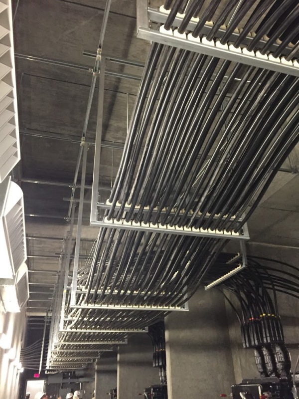
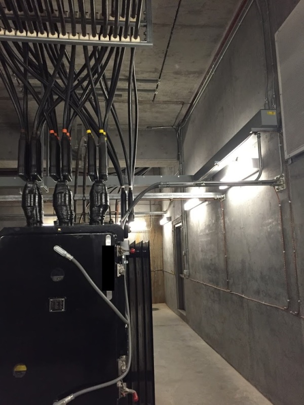
I have ETAP. It most definitely is not capable of modeling and determining current sharing by individual cables in a cable racking system like this:

IMG_4024_xvxusg.jpg
 
wroggent,

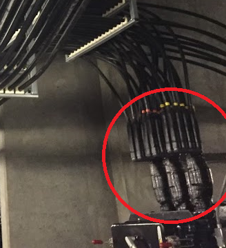
Have you got a close-up or a drawing of whatever that transition arrangement is where the cables joint the transformer? it's very different to anything we use over here.
 
To support further calculation and understand the cause of current imbalance, we suggest to measure with a clamp amp meter the current on each cable at the beginning and the end of the tray to determine the location and cause of the current imbalance.
If there is significant current induction by other feeder, particularly in the transition areas, check if there is a possibility to shield this region to minimize the imbalance effect.
 
Yeah, that's the one - it has attracted my curiosity because it is quite different to what I'm familiar with on LV gear. We normally have a cable termination box where the armour (if any) ends at a gland and the conductors terminate to a palm connector within the box. The palm is sometimes a bushing through the wall of the main tank, other times it may be part of a disconnection link. We do use vertical bushings on the tank top for connection to bare bars, but that's typically at higher voltages.
 
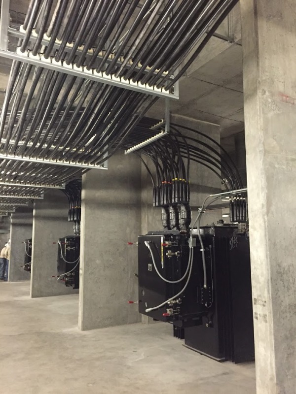
In the very bottom of the picture is a Richards 313 network protector. It is a throated connection to the transformer to the right. This is a 5 x 2MVA 480V spot network system. On top of the network protector are Bussmann 5000 amp KPRC fuses. On top of the fuses are HOMAC flood seal connectors (175 series I believe). The cables are just ordinary xhhw-2 600V aluminum 750MCM - no shield or armor.

IMG_4027_u3j01c.jpg


IMG_4019_jzex6q.jpg
 
Thanks. Now I've found those items on the web I can see how it goes together. I hadn't realised what the network protector was, and the spreader plates above aren't something we see in that form. The whole thing wrapped in tape doesn't give much away. My little bit of learning for today. :) Time for a beer!
 
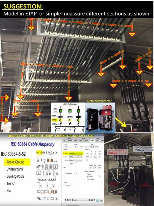
Beside the picture, this is what we know about your system, questions and suggestion:
• The installation consists of 9 -3 x r-y-b trefoil groups ?
• The current sharing between phases is imbalanced greater than 10%.
• This is a 5 x 2MVA, 480V spot network with a Richards 313 network protector & 5000 amp KPRC fuses. (primary side ? )
• What is the voltage and ampacity on the secondary side?. There is any single phase connected load that is causing current imbalance?
• Appears that there are primary and secondary feeders running in parallel. Please confirm
• Consult with ETAP to model the above ground cablesystem per IEC 60364 by section as was suggested. Measuring ampacity is another option in lieu of calculation.

Cable_Air_-_Tray_sk3mhp.jpg
 
cuky2000,

Thank you for the suggestion. I am not the OP; I am not aware of any issues at the site I posted pictures of. I don't have the IEC 60364 module nor have I ever worked with IEC standards but I'll look into that.
 
No particular expertise claimed here, but I see something that reminds me of a story.

<story>
Some of my friends were assembling a three phase generator, and didn't have a single large or trefoil bushing to get the connecting cables through the steel wall of the termination box, so they used three individual bushings, one per phase, in three distinct holes. When they fired up the generator for testing, the wall of the terminal box in between the three bushings got very hot very quickly.

You can probably figure out why.

</story>

WRT to the wires suspended from the overhead, I see two arrays of wires suspended above two metal channels, which are themselves suspended by similar verticals, presumably connected to metal structures above.

I.e., half the wires are going through one aperture surrounded by steel, and half the wires are going through a different aperture surrounded by steel. ... sort of as happened to my friends' generator.

Whereas, if the upper horizontal channel were installed upside down, so that the wires were hanging below it instead of above it, all the wires would be going through the same aperture surrounded by steel.


Mike Halloran
Pembroke Pines, FL, USA
 
Status
Not open for further replies.

Part and Inventory Search

Sponsor