Continue to Site

Eng-Tips is the largest engineering community on the Internet

Intelligent Work Forums for Engineering Professionals

  • Congratulations KootK on being selected by the Eng-Tips community for having the most helpful posts in the forums last week. Way to Go!

Custom valve design and seating pressure

Status
Not open for further replies.

Caliberdesign

Mechanical
Jul 20, 2016
6
Hi Guys,

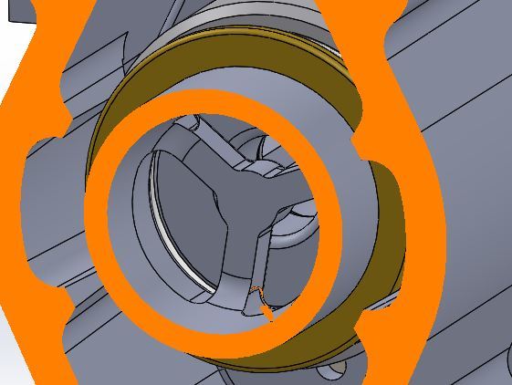
I am working with a prototype in which we designed a valve seating against an Oring. Please see attached. To seat the valve there is a spring force and a pressure force as indicated by the arrows. The valve works well for our pressure range 0-600 Psi. The problem is when a colleague tried to scale up the design 2x the diameter and the pressure in the scaled version will not hold above 350 PSI. I have also attached the cross section of the Scaled up version.

My gut feel would have said this new scaled design should work also. We could not scale the seating spring proportionally but in theory it will be the air pressure that mainly acts to set the valve. Spring seating force around 7 Kg. Air pressure seating force at 500 PSI is around 30kg for the scaled version and 18kg for the non-scaled version. We used a ratio of the circumference lengths to scale up the seating pressure force.

I have heard i should aim for a pressure between the two faces sealing faces of 2x the pressure i am trying to seal against. I this correct? It is a little hard to calculate as is it sealing on an Oring and the exact deformation on the sealing area is unknown. The other issue could be with air escaping around the back of the Oring. The Oring in the scaled version was not given as much squash in the cross-section. Around .3mm for a 5.33mm CS Oring. The working design has a 0.5mm squash in a 5mm CS.

Would be very interested to hear any thoughts. Am i missing anything obvious as to why the scaled version is not working?

Many Thanks,
Will

 
 http://files.engineering.com/getfile.aspx?folder=eece2375-1fa5-4fc8-8f26-268a82109e6d&file=Scaled_version.JPG
Replies continue below

Recommended for you

May I ask if the non scaled valve is your company design or one you purchased and is trying to scale it up using your own design?
Where are you located?
Can you provide real manufacturing 2D detailed drawing section view with dimensions and tolerances? The photos mean nothing. It is not clear how the plunger is guided and stopped.
 
Can you add on the drawing the inlet and outlet sides of the valve?
 
Maybe its me but I can't see how the air pressure is acting on the piston like device.

It seems to me as if the only sealing force is the spring force on the O ring, which is being subjected to a pressure coming from the side of it which is unusual for an O ring.

Maybe there is a better diagram which explains this better?

Remember - More details = better answers
Also: If you get a response it's polite to respond to it.
 
What actuates the valve? How concentric is the actuation force? Is the only thing guiding the piston to the seat the part of the poppet (sliding member) that protrudes into the outlet tube (area labelled "atmospheric pressure")? It looks to me like you didn't scale the length of the part, i.e. did not increase length of engagement, and are probably getting some binding and/or misalignment of the poppet.
 
Also, calculate the force margin of the two valves, i.e. what is the closing force acting per linear inch of seal length per unit of inlet-outlet pressure differential. LI, if you look, the seal line (line of contact btwn seal lip and o-ring) is outboard somewhat from the piston o.d. where the sliding o-ring lies, this differential area gives rise to a closing/seating force in addition to what I assume is a spring acting where he has the arrows drawn). Is the oring the same section size between the two designs?
 
Ok, I get you, but it looks a very small area. I'd like to see how those forces were calculated.

Remember - More details = better answers
Also: If you get a response it's polite to respond to it.
 
I have never seen a valve seat designed like this, and I think there are good reasons they are not. This design does not support the o-ring well, so the ring is likely to extrude. Also, the parts have to be very well aligned to get a good seal and the o-ring is likely to move under pressure and lose its seal. (o-rings are supposed to move under pressure to create a tighter seal)

A metal lip, as shown, should seal against a flat rubber surface that is well constrained in a groove. Or, an o-ring in a groove is supposed to seal against a flat metal surface.
 
CompositePro said:
I have never seen a valve seat designed like this, and I think there are good reasons they are not. This design does not support the o-ring well, so the ring is likely to extrude. Also, the parts have to be very well aligned to get a good seal and the o-ring is likely to move under pressure and lose its seal. (o-rings are supposed to move under pressure to create a tighter seal)

A metal lip, as shown, should seal against a flat rubber surface that is well constrained in a groove. Or, an o-ring in a groove is supposed to seal against a flat metal surface.

I would agree with CP's assessment.

This looks to me to be a design that needs significant modification to work as intended.

I also do not see how the air pressure behind the poppet adds to sealing force.

Also- if you doubled the CL diameter of the o-ring and used the exact same seating force, you have halved the contact pressure between the poppet and o-ring.
 
I agree - I think the end of the piston should be a T shape to present a flat face to the O ring which would stand slightly proud of the groove rather than trying to impinge on only a small area of the O ring which is liable to move vertically in the sections shown.

Still need to see how those forces were calculated though.

Remember - More details = better answers
Also: If you get a response it's polite to respond to it.
 
It's a small area, and it may vary if the o-ring gets permanently distorted.

"Still need to see how those forces were calculated though."

We are ASSuming the calculation was done from the start...;)
 
Thanks for the input.

I will try my best to answer the questions.

"Also, calculate the force margin of the two valves, i.e. what is the closing force acting per linear inch of seal length per unit of inlet-outlet pressure differential. LI, if you look, the seal line (line of contact btwn seal lip and o-ring) is outboard somewhat from the piston o.d. where the sliding o-ring lies, this differential area gives rise to a closing/seating force in addition to what I assume is a spring acting where he has the arrows drawn). Is the oring the same section size between the two designs?


btrueblood -Yes. The valve is designed so that the O-ring shown to left has a smaller sealing diameter than the O-ring to the right resulting in pressure force to the right. the difference in diameters converted to areas ie. (pie*("sealing diameter 2"/2)^2 - pie*("sealing diameter 1"/2)^2)*pressure = Seating force. Like i said i scaled the seating force in proportion to the circumference length in attempt to create the same sealing pressure between faces. Since i don't know the deformation of the oring the sealing pressure is a little unknown but i figure this logic will at least give it the same sealing pressure as the un scaled version. I works out at around 0.236kg/mm or around 13 lb/in as you Americans like it. The oring CS is 5mm. Does this seating force sound like enough?

The valve is actuated by a central rod and closed again by the valve spring acting in the location of the arrows. Too much seat force and i am worried the actuator will not be able to open


"I have never seen a valve seat designed like this, and I think there are good reasons they are not. This design does not support the o-ring well, so the ring is likely to extrude. Also, the parts have to be very well aligned to get a good seal and the o-ring is likely to move under pressure and lose its seal. (o-rings are supposed to move under pressure to create a tighter seal)
A metal lip, as shown, should seal against a flat rubber surface that is well constrained in a groove. Or, an o-ring in a groove is supposed to seal against a flat metal surface.


The original design was using a flat washer type seal as you describe but we moved in favor of an off the shelf O-ring. In two prototypes the un-scaled version works perfectly, no issues with O-ring retention. It actually seems to seal more reliably than the previous flat seal design.

Yes the length was not scaled, only the diameter which could cause some twisting and binding of the valve (racking). There is a brass ring that keeps the the inner valve or poppet/piston concentric as shown below. the fit is actually loose on the scaled version. From what you guys have said this might be the problem... I am in two minds about flattening off the sealing valve face as I will get increased sealing pressure with a small sealing ridge but also increased sensitivity to misalignment.

cross_section_nlwte4.jpg
 
caliber design,

Your calculation for the sealing force from the available ring looks far too big. Where is 2" and where is 1"??

The only available area for the high pressure air to act on is a very small ring between the centerline of the O ring and the outside of the main valve sliding element.

This is a very small fraction of the valve sliding cylinder diameter, from your drawing about 3-5% of the OD.

I think your air pressure sealing force is not as big as you think, hence for the small version the spring force works OK, but for the bigger one it isn't enough.

A dimensioned section drawing would help here.

Remember - More details = better answers
Also: If you get a response it's polite to respond to it.
 
Ok, so the pressure force is more or less equal between the two. I see the brass ring, and depending on how tightly toleranced it is to the guide ribs, you may or may not get binding - it's easy enough to check this in a decent CAD program.

To your force balance, you are missing the o-ring drag/friction force from the sliding seal, and the spring force. Figure the sliding seal drag scales proportionately to the diameter or stays at a fixed value (I can argue either way), but you say the spring force did not scale. Look into pushing the outboard seal further outboard to compensate for the "missing" amount of spring force that didn't scale up, and/or to compensate for a proportionate increase in sliding seal drag. Looks like it would be quickest/easiest to do this by machining a slightly larger o.d. seat (push the static seal o-ring to a slightly larger diameter), at least to test the theory.

Looks like a bash valve for a pneumatic air gun?
 
LittleInch, btrueblood thanks for the replay. Sorry that was some poor equation writing its not 1" but meant to read (sealing diameter 1) as in the oring to the first Oring to the left in the picture. At around 500PSI it doesn't take much area to get a significant force and yes it is around 5% of OD.

here's the actual figures for the unscaled valve: pie*(26.8/2)^2-(25.4/2)^2 = 57.4mm^2
57.4mm^2*0.3516kg/mm^2 (500PSI) = 20kg then i scaled up the closing force by 1.85 times due to the ratio of diameters from scaled to unscaled: 50/27=1.85 (scaled diameter was 27 now 50) then 20kg *1.85 = 37kg. This meant i increased the radius of outboard seal by 0.72 mm in that of the inner. In reality i actually scaled to 0.8mm increase give me around 40kg of closing force. I didn't think about the ring friction force but for the scaling exercise i don't think i need to consider as it will be present in both systems proportionately. If I had a pressure i was trying to achieve on the outboard seal then i would include it but for this i need to know the amount of deformation of the Oring to get a contact area. I would also need to have a target. Trying to seal against 550PSI air what should my seating pressure be?

Your right btrueblood i should have included the spring force: 20kg (pressure force) + 7kg (spring force)=27kg , 27*1.85= 50 (total force), 50-7kg = 43kg So 43kg should be new target. 3kg more than what was designed.

I still have a feeling that the scaled valve does not work due to misalignment. It seems to me that the scaling calcs while not exact should have give an approximate enough value for the valve to work unless the unscaled valve is right on the limit of not sealing which it does not seem to be. As far as sealing pressures on the static outboard Oring is there a rule of thumb to use? Ie sealing pressure should equal 2x the air pressure at which it is sealing?

Spot on Btrueblood its a bash vavle for a pneumatic gun
 
For alignment, can you not extend a rod or similar member from the end of the piston, and have it slide inside the end wall opening (where I assume the bash actuator rod is coming thru)? You'd have to shorten the bash actuator rod to make it all fit...

I thought I'd seen a similar idea posted on another forum, I think I replied there too. If my idea works, can I help beta test? :) I'd also accept a tin of JSB Exact 18gr .22's as payment. Good luck with your endeavors.
 
Good idea, I will have a look into that but might pose a few issues as that hole has a couple of other functions. Interesting that you have seen a similar design. It definitely was not me who post previously. haha different type of gun but I had better not say too much.

Just before i put this to bed i just wanted to make i have sufficient seating pressure. pressure between seating faces = 1.15 air pressure + 70N (spring force). Does this ratio sound about right or too small?


Um, not sure what you are asking. The seal doesn't care where the force comes from. You might care if there is a concern about reliable seating at some low limit pressure, which would then dictate how much spring force you need. Realize there is no such thing as a perfectly-centered spring force from a coil compression spring, you will always have some moment/torque at the end of the spring.
 
Status
Not open for further replies.

Part and Inventory Search

Sponsor