Continue to Site

Eng-Tips is the largest engineering community on the Internet

Intelligent Work Forums for Engineering Professionals

  • Congratulations KootK on being selected by the Eng-Tips community for having the most helpful posts in the forums last week. Way to Go!

Cutting force graph of elliptical vibration cutting

Status
Not open for further replies.

Vxxxxx

Mechanical
Jun 5, 2020
91
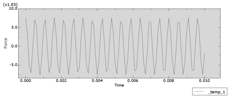
Hi, I dont know how to interpret the graph of main cutting force (Fx) for elliptical vibration cutting process.
For normal orthogonal cutting, Fx value goes up and down but remains above zero value.
But for elliptical vibration cutting, Fx value fluctuates periodically in the range from max positive value to max minimum value(negative value).
1111_w9w1za.png


I understand that the tool is vibrating elliptically and periodically but I dont know how to explain negative values of the Fx.
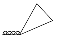
I am using elliptical vibration cutting with separation, means the tool trajectory is as shown below.
3333_bv4wxd.png


Since the tool cuts the workpiece and leave the workpiece, and so now, when the tool not in contact with the workpiece, why is Fx a negative value instead of zero value?
 
Replies continue below

Recommended for you

Check the article "Analysis and modeling of force in orthogonal elliptical vibration cutting" by W. Bai et al. It features a plot of force vs time and you can see that cutting force (in the feed direction) is always positive or zero while thrust force (normal to the feed direction) can be also negative. Thus you should check the axes and make sure that you plot proper component of the force. Also, which output variable do you use ?
 
Noted. The output variable that I am using is RF1.
 
Is this due to inertia of the tool itself in your prescribed motion? Force = Mass * Acceleration
Compare this to results from an elliptical model that does not cut anything.
You may get a different value looking at the reaction force constraining the mostly stationary workpiece.
 
Maybe you are right, let me try that out. Thank you oldNail, and FEA way.
 
@oldnail, it seems like youre right, i get similar graph with elliptical model without cutting the workpiece. But the max and min values of RF1 is slightly less than elliptical model cutting the workpiece.

If its inertia, then the negative values make sense as the acceleration is negative values when the tool is vibrating backward.
I am trying to compare cutting force between orthogonal cutting and elliptical vibration cutting.

So I can just take average of this graph and compare it with average cutting force of orthogonal cutting?
or is there anything else I should do? Thank you.
 
Sure, you can try filters or simple subtraction since you know the exact mass and acceleration of the tool. You could even use the results from your model where you're not cutting anything.
Another method, as I suggested, might be to examine the reaction force constraining your workpiece instead of the moving tool.
 
I understand the subtraction approach but not the second approach where I could just take the model not cutting anything.

If I go with approach 1, it means that force(cutting workpiece)-force(not cutting workpiece) to get the actual cutting force.

If its second approach, it means that my cutting force entirely depends on the tool and workpiece material is irrelevant. Does that mean that I have to assume that the force generated by the tool is so large that the contact with the material can be ignored?

As for the third approach, I am currently taking force from a reference point on the tool. If I were to examine reaction force constraining my workpiece, what would be my reference point?

Thank you very much.
 
What I meant was you can subtract the tool RF from model without cutting anything from the tool RF when it is cutting your workpiece.

And/or the RF constraining the workpiece should be equal and opposite to the cutting force, right? If you don’t have it at a ref point then just make a kinematic coupling, constrain its ref point, and record RF.
 
Okay Noted. Thank you very much oldNail!
 
Hi @oilNail, whenever I use kinematic coupling on my workpiece, it doesnt work. is it because it overlaps with the boundary condition exerted on the workpiece?

 
If you’re constraining the part using a kinematic coupling then any other constraints are redundant.
 
Status
Not open for further replies.

Part and Inventory Search

Sponsor