Eng-Tips is the largest engineering community on the Internet

Intelligent Work Forums for Engineering Professionals

  • Congratulations waross on being selected by the Tek-Tips community for having the most helpful posts in the forums last week. Way to Go!

datum feature question

Status
Not open for further replies.

lowerp

Mechanical
Oct 29, 2021
7
0
0
US
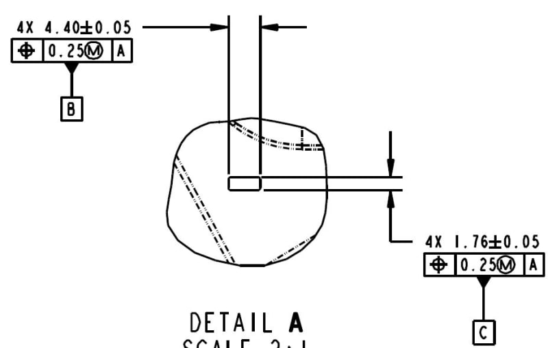
I have a dash bezel designed with 4 rectangular pins that are used for locating and affixing this part to the dash at assembly. All 4 rectangular pins are equal size, length, and will be pressed onto the dash "equally". I want these 4X pins to be my datum feature B. I plan to have two position tolerances for the pin, one for the length and one for the width. Do I then attach the datum feature B symbol to each position tolerance FCF? Using ASME Y14.5-2009.
 
Replies continue below

Recommended for you

Which feature locates the pins? The size or the length? Or none?
A picture would be very helpful.
4X size and tolerance and position with no datum and then attach datum feature B to the feature control frame.

But maybe my understanding is incorrect.
 
Technically the 4 lengths and the 4 widths are different features and different datum features. If they are of equal importance and you want to treat them equally at the datum precedence order you could label one group as B and the other as C and then in the feature control frame that references them would reference A (primary), B-C (secondary).

In the 2009 version of Y14.5 which you use it's called Multiple Datum Features.
 
I believe this reflects what Burunduk is stating, minus the FCF.

datum_pic_horvax.jpg
 
lowerp,

How the part is assembled? Which one is taking precedence: B or C? Or both?
Again, as I stated before, an assembly figure/ drawing/ picture would be helpful.
We would like to find what is exaclty the design intent. Based on your written description above that might be insufficient.


A unilateral profile of surface tolerance makes more sense. Set the mutual perfect contact boundary for each side of this assembly and then each part will be given a maximum variation from that. If there is an interference fit then overlap the boundaries at the maximum allowable interference and set the total profile of surface tolerance to the determined minimum interference that is acceptable.
 
lowerp said:
I believe this reflects what Burunduk is stating, minus the FCF.

Yes it does.
And it is up to you to decide whether to reference them as B secondary and C tertiary, C secondary and B tertiary or B-C secondary in the feature control frames where they appear. I assume the primary datum feature is one of the large faces of the dash bezel, perpendicular to the rectangular pins, and in the functional assembly, it probably constrains 3 degrees of freedom. One of the important degrees of freedom that it doesn't constrain is the rotation around the pins. Both groups of datum features B and C are capable of constraining that rotation. If there is no priority to neither in applying that constraint, they should be referenced secondary as B-C (or C-B since it doesn't matter). The constraints of the two remaining translational degrees of freedom are only geometry-related anyway, and not affected by the choice of datum precedence order. The important thing in this case is to capture how the orientation (rotation) is constrained.
 
Status
Not open for further replies.
Back
Top