Continue to Site

Eng-Tips is the largest engineering community on the Internet

Intelligent Work Forums for Engineering Professionals

  • Congratulations SDETERS on being selected by the Eng-Tips community for having the most helpful posts in the forums last week. Way to Go!

DC compound motor control schematic 4

Status
Not open for further replies.

edison123

Electrical
Oct 23, 2002
4,501
Drive gurus

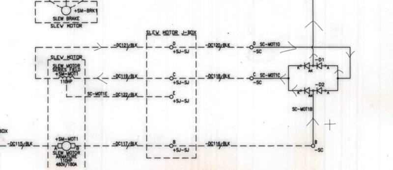
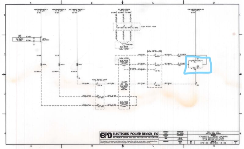
Please see below a DC compound motor control schematic.

What is the function of set of 4 diodes on the right (marked in blue) that feed the series field?

Are they for ensuring the series field current direction is unidirectional when armature voltage is reversed for rotation direction reversal (hoist up/down)?

How do they work? Thanks for your inputs.
DC_compound_motor_control_ynbdp9.jpg


Muthu
 
Replies continue below

Recommended for you

You may be correct.
Without the diodes, the series field would cause field weakening and greater speed when the armature current was reversed.
At one time I was responsible for a number of DC drives, but they were all shunt motors, direct connected to MG sets.
The MG outputs were controlled by Amplidynes.
I notice what looks like three phase going to brake motors.
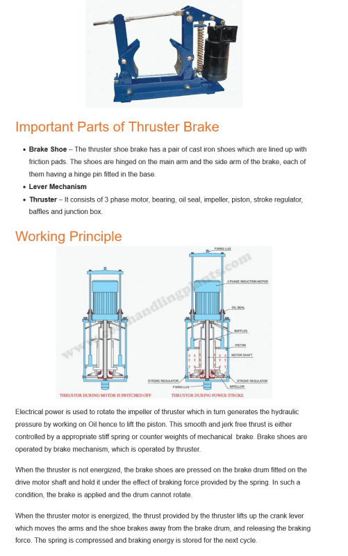
Are those Thrustor brakes.
Spring applied and hydraulically released by a centrifugal pump.
The cylinder was vertical and flaired at the top. When the piston reached to top of the cylinder, the oil bypassed and returned to the sump.
When the power is removed and the pump stops, the hydraulic fluid backflows through the pump and the brakes are spring applied.
That system gave a nice application rather than an abrupt brake application.
It was also suitable for brakes that were too large for a reasonably sized solenoid.

Screenshot_2023-05-08_at_21-38-14_Thruster_Brake_-_Coal_Handling_Plants_raz8iw.png


--------------------
Ohm's law
Not just a good idea;
It's the LAW!
 
Diodes keep same current direction on series field when motor voltage polarity is reversed (motor direction change).
So, series field remain in same direction and avoid high voltage development at current reversal also.
 
Thanks, Bill and iop.

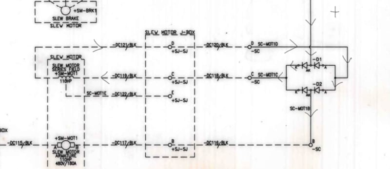
I am trying to visualize the current flow path via the diodes for both positive polarity and negative polarity and am stuck.

Muthu
 
I recommend using colored pencils/pens/computer markups. Pick a color. Mark one side + and the other side -. Trace current paths from + to -. Pick a different color and reverse the polarity marks. Trace current paths from + to - again.

xnuke
"Live and act within the limit of your knowledge and keep expanding it to the limit of your life." Ayn Rand, Atlas Shrugged.
Please see FAQ731-376 for tips on how to make the best use of Eng-Tips.
 
The interpoles are always in series with the armature.
The purpose of the interpoles is to mitigate the distortion of the magnetic flux in the air gap caused by the armature.
The purpose of the series field is to strengthen the shunt field.
If the current in the series field reversed when the armature current reversed, the series field would weaken the shunt field rather than strengthen it.
Hence the bridge diode so that the series field remains the same polarity as the shunt field.
Note that the diodes must carry full armature current.

--------------------
Ohm's law
Not just a good idea;
It's the LAW!
 
I have used a bridge diode to protect electronic circuits when there was a real possibility that the battery may be installed backwards.
No matter which way the battery was installed, the electronics received the correct polarity.

--------------------
Ohm's law
Not just a good idea;
It's the LAW!
 
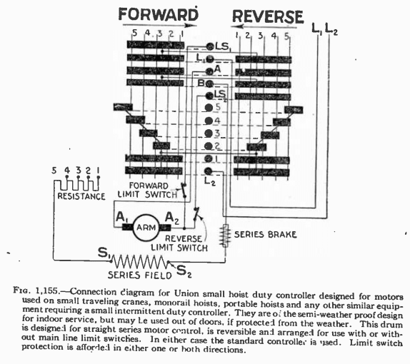
I support the idea that the diodes are intended to keep the field pointed in one direction when the armature is reversed, so that torque and rotation will reverse, is supported by the clip from audel's of a series motor controller below. The diagram describes a reversing 5 step drum controller. One end of the field is always connected to L2 when energized, so the magnetic field of the series winding is always pointed the same direction. The armature is connected to the section of the controller that reverses the armature polarity, and as a result reverses the torque direction.

So the control arrangement of this dated technology is the same as is shown on the drawing (except no freewheeling diodes to save contact wear).

Screenshot_from_2023-05-10_18-56-07_xxzpmw.png
 
Status
Not open for further replies.

Part and Inventory Search

Sponsor