Continue to Site

Eng-Tips is the largest engineering community on the Internet

Intelligent Work Forums for Engineering Professionals

  • Congratulations SDETERS on being selected by the Eng-Tips community for having the most helpful posts in the forums last week. Way to Go!

De-magnetization with LC Circuit

Status
Not open for further replies.

LL631

Industrial
Nov 30, 2018
24
I have a DC electromagnet which has problems with residual magnetism, is it feasible to place a capacitor in parallel with the coil to act as an LC oscillating circuit in order to de-magnetize the magnet when the power is removed? i.e. if I sized the capacitor so that when the supply was removed the under damped response would create a decaying AC voltage over the coil, de-magnetizing it?

If this is possible am I correct in saying that I would need to size the capacitor so that the Q factor > 0.5 in order to create the underdamped response? Then how would I determine the required underdamped frequency to cause de-magnetization?
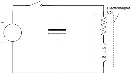
De-magnetising_Circuit_lhv1qb.jpg
 
Replies continue below

Recommended for you

Just throw in a capacitor and see what you get. Can't give you any numbers 'cause you didn't provide any.
The technique usually works well. But if R is dominating, you will not see any oscillations. That is rare, though.

Gunnar Englund
--------------------------------------
Half full - Half empty? I don't mind. It's what in it that counts.
 
I think you will not get sufficient oscillations to do useful demag. I suspect you will be disappointed with the results but do show us some current waveforms. Your question of frequency makes no sense since this is a transient DC circuit. I would concentrate on improving the electromagnets design or materials/heat treatment.

----------------------------------------

The Help for this program was created in Windows Help format, which depends on a feature that isn't included in this version of Windows.
 
I think you need a switch between the capacitor and coil. Charge the capacitor first then open the charging switch and close the switch to the coil. This would best be done with a single pole double throw switch. You may want to add a resistor on the supply side to limit the charging current.
 
We used to have demag units that we connected to the 60Hz line.
When turned off they would ring down, it would take a few seconds for the field to decay.
They worked well.
You will need to connect to AC for the deamg cycle.

= = = = = = = = = = = = = = = = = = = =
P.E. Metallurgy, Plymouth Tube
 
You are talking about a DC magnet, I assume it is a soft magnet core? If the core is very soft (magnetically), low frequency can work. I ever manually demag permalloy by switching the polarities of a DC field (decrease current simultaneously). if the core material is semi-hard, or hard material, you will need a higher frequent, higher field.
 
Thank you all for the replies, can't test anything this week but hopefully can get get time next. There seems to be conflict whether this should work or not so I'll provide more detail in the hope to get a better understanding.

So, the problem is the magnet will sometimes fail to disengage due to residual magnetism. Thick chrome plating to create an non permeable gap resolves the problem but affects holding strength, hence the idea to find another solution. The EM is a DC 24v holding magnet: V=24V, R=49ohm, L=?. The core & counter latch plate is made from untreated 11SMn30 0.1% low carbon steel (semi soft.. not sure?).

I intended the circuit to work as follows:
- Switch closed, capacitor charges & coil builds magnetic field. I assume the capacitor will "rob" current from the coil until it is full then act as an
open circuit.​
- Switch open, capacitor discharges through the inductor until it is empty, charged inductor then discharges through capacitor in reverse polarity until
it is empty, this oscillation will continue but decay due to resistance losses. The frequency & duration of decay being linked to the capacity of capacitor/inductor.​

I guess the question is A. will the circuit work like this? B. if so, will the amplitude, frequency & duration of AC decay be sufficient to cause any demagnetization? Is there anyway to work this out? Or is it a case of going with Skogsgurra's suggestion and throwing in a capacitor to see.


Yes, do. But make sure the cap isn't polarized (electrolytic). Hook a scope across the winding to judge the result. Or use drop-out time. You will probably land somewhere between 10 and 100 uF. Which is a rather large capacitor. But the low working voltage, select 35 V to have some head-room, makes it feasible.

Gunnar Englund
--------------------------------------
Half full - Half empty? I don't mind. It's what in it that counts.
 
An anneal will help reduce the remanence but plating is generally used as it not only breaks the circuit but also reduces wear and corrosion. It does not need to be thick. 5 microns of electroless nickel will do wonders. It's going to be a big capacitor to get under damped oscillation. Probably too much resistance to achieve significant demag but love to see some current wave forms.

----------------------------------------

The Help for this program was created in Windows Help format, which depends on a feature that isn't included in this version of Windows.
 
Cr-plating only acts as an air gap to weaken the force, it does not nothing to demag the residual/remanence. 11SMn30 is a free machine alloy with high S/P addition that makes it "hard". Choosing a softer core material (or anneal if applicable) can fundamentally eliminate (practically) the residual.

Adding a capacitor sounds a good idea, which is the principle of "De-Magnetizer". one concern is, does that create only a few cycles of DC? the other is, does the DC at the last cycle small enough NOT to re-magnetize the core?
 
I had some junk laying around. So I tested what really happens. I used a transformer core with a 1200 turn winding with rated DC voltage 12 V. Resistance is 13 - 14 ohms and inductivity (with yoke in place) is just under 3 H. Pictures:

Code:
[img]https://res.cloudinary.com/engineering-com/image/upload/v1548236812/tips/EngTips_Demagnetizing_lifting_magnet_w_capacitor_1_tji0jd.png[/img]

I hope that this encourages you to test with your device. Please note that the capacitor voltage MAY get a bit higher than I presumed. Especially with low capacitance values.

Gunnar Englund
--------------------------------------
Half full - Half empty? I don't mind. It's what in it that counts.
 
Status
Not open for further replies.

Part and Inventory Search

Sponsor