Eng-Tips is the largest engineering community on the Internet

Intelligent Work Forums for Engineering Professionals

  • Congratulations waross on being selected by the Tek-Tips community for having the most helpful posts in the forums last week. Way to Go!

Deactivate failed ROD elements 2

Status
Not open for further replies.

filippo_a

Aerospace
Sep 26, 2018
6
0
0
IT
Good morning,
I am simulating the collapse of a truss structure (ROD elements, SOL400) and I would need to eliminate from the structure the elements as soon as they reach the critical value of strain.
Thank you very much for your help.

Kind regards,

Filippo
 
Replies continue below

Recommended for you

well i am not familiar with Nastran (anymore) but the program should do that automatically
Most structural calculation program nowadays have special nonlinear elements that can handle such things

 
Hi I am not sure (have not found it). If you find out please let us know, it could be interesting for others too.

In Strand7 there is a nice element called the cut-off bar, which has a brittle failure criteria, which essentially removes the element when the axial force is higher than a given user defined value (max tenison or compression).
 
Hi
I don't know about SOL400, but in SOL601 you can use a stress-strain function for the material and when the limit for the curve's data is reached the element will fail.

Perhaps something similar is possible in SOL400.

Thomaas
 
The strain stress curve is typically plastic, with our without hardening, so it is not the same as removing an element (it is still there, with some small stiffness). In a stress strain curve one can not normally have a brittle failure (or negative slope) since this could lead to a solver instability (negative stiffness). Typically if one exceeds the table, the last two points are used to extrapolate the curve further out, not seen that something would fail suddenly. Actually as ThomasH mentioned, in NX Nastran there seems to be an option in SOL601, to set a parameter ( so that the curve is not extrapolated (as default I assume), but instead the element fails (did not know that). Now not sure which Nastran you use, because this seems available in NX, and not in the MSC one.

The closest I can get is to a cutoff bar as mentioned, is to have a CBUSH1D (MSC Nastran) with a a force displacement curve that drops to zero after a critical axial force has been reached in the element. Now the geometric nonlinear formulation, between the CBUSH and CROD I do not know if it is exactly the same, but for geometrically linear analysis a truss is pretty much the same as 1D spring if the spring axial stiffness is equal to the truss EA/L (truss stiffness).

I have not been able to find another way than the cbush1d element with a brittle failure curve, but having said that there might and must of course be a better one :).
 
The above method of using a CBUSH1D with a brittle failure force-displacement curve should work (I have tested it in Strand7 and it is OK. Below an image of the cutoff bar elements at the bottom with failire at 1 N and at the top 3 spring elements like CBUSH with a nonlinear force displacement curve for brittle failure; reults are almost the same, red and blue graphs show axial force in the failed cutoff bars and spring elements respectively).

Capture_apktw7.jpg
 
Take a look at the CBUSH element with a PBUSH + PBUSHT entry defined.

On the PBUSHT entry, for the KN type of definition (nonlinear spring), the continuation field FUSE allows the CBUSH to be deactivated, or reduced in stiffness, depending on the chosen option. The other continuation fields work in conjunction with the FUSE option, so read the remarks of the PBUSHT entry.

DG
 
Hi everyone, I'm very sorry for replying in such a delay. I would like to thank you all, you gave me very useful advices.
I've tried all of them but actually I had many problems in adapting the methods to my structures, most of all for a reason: PBUSHT works perfectly as I need, but it only applies to PBUSH elements which act like beam elements instead of rod elements, so they don't only react to axial loads. As of PBUSH1D, as I mentioned, PBUSHT property isn't available so I can't get failed elements deactivated. Any other idea?
Thank you very much in advance.

Filippo
 
The CBUSH + PBUSH + PBUSHT combination can be configured to use only the directions you need, so you can simulate a ROD type connection by only supplying a value in the K1 field on the PBUSH entry (leave the other Ki fields blank) + only the KN field TKNID1 (to reference a table) for the axial direction only (leave the other TKNIDi fields blank). Set the FUSE field to 1 and the DIR field to 1.

DG
 
Yeah, thank you very much. I've always been putting 0 in the other Ki so it turned out to get singulatities every time. Leaving them blank is the exact solution and everything works as I wanted, thank you very much again for the bother.
Actually now I'm facing another problem: since I need my structure to translate over a plane with friction, CBUSH elements seem not to be supported by contact load. To be more clearer: I need my truss structure to be dragged over a plane and let it collapse because of the stresses induced by the friction (together with other loads). Originally, when using CROD elements, I figured it out as a motion of my structure - with applied a deformable contact body load - over a surface with a rigid body contact load. But now, trying to do the same with CBUSH elements, it seems not to be possible.
Any suggestions maybe?
Thank you very much again.

Filippo
 
It's difficult to make specific suggestions without knowing the details of the geometry. The CBUSH element cannot be used as a basis for generation of a deformable contact body because it does not have any geometric properties. rods, beams, plates and solid all have geometry, explicit or implied through section properties, so they may be used to define a contact body. There is nothing to stop you connecting any of these elements to the GRID points where the contact occurs, while retaining your CBUSH elements to model the collapse at fuse load. The elements you add to allow contact to be defined do not have to form part of the load path that affects the collapse condition; you only need to make sure the added "geometry" elements are kinematically constrained so as not to cause instabilities in the solution.

For more specific comments, I would need more specific details of the model.

DG
 
What I am trying to simulate is an abrasion phenomenon, studied through the principles of the peridynamic theory: it is part of a project that wants to reach an union between this theory and the FEM method, and considering the abrasion, this kind of investigation is quite new. As it can be seen in the image the structure looks like a quite intricate truss structure which connects many points. The aim of the simulation is to reproduce the abrasion, that is the failure of some truss due to the friction with the plane over which it is dragged (green lines are part of the surface that originally acted as the rigid plane).
Thank you very much.

Filippo

Immagine_heccz4.png
 
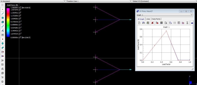
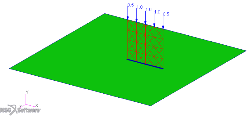
So, if I am interpreting the view correctly, the truss structure is perpendicular to the rigid plane, right? I am also interpreting that the lowest row of GRID points in the view are all in contact with the rigid plane. Now you apply some loads somewhere which tend to cause the truss structure to slide across the plane, and you want to know if, and where, the structure fails (exceeds some nominal load value - hence the fuse).

If this interpretation is correct, what pushes the truss structure into contact - in other words, what sort of load develops the loads normal to the plane from which friction forces will emanate? Gravity, some press type loading?

DG
 
Here is a small example of a truss type structure connected by CBUSH elements. The structure is placed on a rigid plane on its edge so it is normal to the rigid plane and just touching it along one of the edges of the truss structure. Along the edge in contact, CBAR elements are also connected to the GRID points, but these CBARs have a small section dimension and low value Young's modulus for their material. The goal of the CBAR elements is to provide the geometry for the contact with the rigid surface. The top edge of the structure is fixed in the Z direction as a guide and prevents the structure tipping over.

Step 1 applies a vertical load to push the truss structure into contact with the rigid plane. Small value linear springs are used to stabilise the model, as there is a rigid body mode in the X direction until load develops at the contact surface and friction stabilises the problem.

In a second step, the GRID point at the top left of the truss structure is then loaded in the -X direction to pull on the truss structure. As the load is increased, eventually the loads in some of CBUSH elements of the truss exceed the limits defined by the FUSE levels. This occurs somewhere between load factor 1.7 and 1.8.
fuseit_cdkiow.png

DG
 
Status
Not open for further replies.
Back
Top