Continue to Site

Eng-Tips is the largest engineering community on the Internet

Intelligent Work Forums for Engineering Professionals

  • Congratulations IDS on being selected by the Eng-Tips community for having the most helpful posts in the forums last week. Way to Go!

Deep Excavation 3

Status
Not open for further replies.

dik

Structural
Apr 13, 2001
25,841
I have a project. It is a fairly large/deep excavation, with rolled steel soldier piles and walers. The excavation is approx 7m (25’) x 9m (30’) x 11m (35’) deep. It’s constructed in plastic clay with the odd sand/silt seam. The watertable is approx 20’ from the bottom. The effect of the groundwater is causing substantial pressure loads on the soldier pile shoring system.

The area of the excavation (site) is drained by means of shafts drilled into bedrock and is removing water from the aquifer as well as the site. Is it possible to determine the effectiveness of the shafts for pulling down the groundwater table? Can a series of dewatering shafts around the perimeter pull down the groundwater table? How can the effects of the groundwater be eliminated?

The clay component is relatively impermeable and is nearly saturated (all the time; it is a feature of our highly plastic clays). What effect does this have on the soil pressure? Is it just the saturated soil weight times the Ka? And is this affected by the groundwater, if the water is drained?

Another question... with the soil pressure on the excavation, is it possible for this to cause the base of the excavation to be ‘pushed up’? How would a person calculate this ‘uplift force’? And how would this normally be accommodated, if it happens?

Rather than think climate change and the corona virus as science, think of it as the wrath of God. Feel any better?

-Dik
 
Replies continue below

Recommended for you

Answer to this question

Another question... with the soil pressure on the excavation, is it possible for this to cause the base of the excavation to be ‘pushed up’? How would a person calculate this ‘uplift force’? And how would this normally be accommodated, if it happens?

These question get answered when a getech engineer with soil test data makes the required computations. I assume there are test borings and soil samples suitable for laboratory testing.

As to how effective the "shafts" are in lowering the water table, it depends a lot on the details of those "shafts".

Permeability of the soil must be known to evaluate this in detail. However, general computations usually are suitable to get you in the "Order of Magnitude" of these things, again by a geotech engineer..

Determining the effectiveness of the dewatering you might install wells to measure the location of the water table and observe how well the dewatering is doing. It would be good to have your dewatering wells outside of the sheeting to help relieve pressure on the sheet piling.
 
Is it possible to determine the effectiveness of the shafts for pulling down the groundwater table?

Yes, through known soil layers, the effectiveness can be calculated (this is a design issue). Also, test/monitoring well can confirm the accuracy of the calculation.

...it is a feature of our highly plastic clays). What effect does this have on the soil pressure? Is it just the saturated soil weight times the Ka? And is this affected by the groundwater, if the water is drained?

The earth pressure will be influenced by cohesion. You have to consult with your geotechnical engineer on soil property and the influence/application of ground water.
 
I've just learned that the soil is alluvial and not lacustrine and there is some variation.

OG: I've got a geotekkie involved and I'm looking for technical data so I know what questions to ask. I'm not trying to work around him... just trying to gain an understanding of the conditions. For example, I've learned that often a trapezoidal load diagram is used in lieu of a triangular one and am currently trying to determine which is appropriate... and what, if any shortcomings...

r13: thanks... was aware of those items...

I'm seeking design information, not looking for a design... once I'm comfortable with the loading, then the design part is easy. Is there any information on the uplift of the excavation that I can take a look at/consider... I'm not sure if there is a term for this, or if I'm imagining it can happen...

Rather than think climate change and the corona virus as science, think of it as the wrath of God. Feel any better?

-Dik
 
Is there any information on the uplift of the excavation that I can take a look at/consider...

Head differential between excavation and the groundwater elevation.
 
You will know how effective the dewatering is when you dig for installing each lift of lagging boards. If you dewatered sufficiently to successfully install the boards, the dewatering was effective. If you can't install or can't economically install lagging due to ground water, you should not have used soldier beams and lagging. Lagging cannot retain water. Perched water over an impervious soil layer may not be the same as ground water that extends to or below your excavation subgrade.
Soil mechanics books often describe how to check a sheeted excavation for base stability in soft soils. If the subgrade soils are susceptible to base heave, you may have to use steel sheet piling with sufficient toe embedment rather than soldier beams with no continuous embedment below excavation subgrade.


That's what I was thinking... that the soil pressure would be the Ka * saturated soil weight or something similar... I understand from a similar project within a few hundred yards that there was no issue in installing the lagging... different engineer and 5 years ago... situation hasn't changed... generally if the lagging can be installed without water problems then groundwater isn't likely an issue.


and this is resisted by gravity of soil less water alone, or is there some contribution due to soil shear resistance?

Rather than think climate change and the corona virus as science, think of it as the wrath of God. Feel any better?

-Dik
 
dik, read up on flow net analysis for base stability. However, it will need to consider continuous sheet pile embedment below subgrade. You can't do it with a wall that is lagged just to subgrade. You need embedment to increase the flow path length.

 
Agree with the above comment.

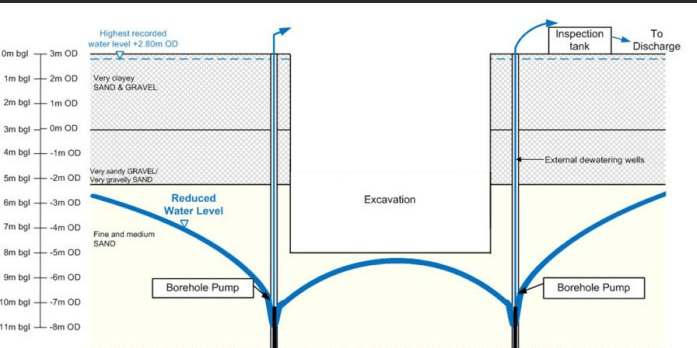
I think it is a stability problem. As soil is to be removed/excavated from a balanced system, and the ground water pressure will cause instability in the imbalanced system. The drawing below depicts excavation and dewatering in the granular soil, that may not fit your situation, though similar.

image_tgcmk2.png
 
For your question dealing with bottom heave,etc. I assume your geotech is drawing flow nets for different situations. Then you can evaluate safety factors against upward upheaval and possible "quick" conditions.. Dewatering wells for construction can be placed where convenient usually, but if these are to remain, site working conditions, such as unloading the feature inside the excavation when all done with the work, then location is important.. When I have done these I stay away from a safety factor of 1.0 (just holding) and shoot for 2.0 if possible. Too many factors to be precise usually. I ditto PE inc. Those deep cut offs really are needed. I'll add. Be prepared for unexpected power loss so you will never have the pumps shut off at the wrong time.
 
Thanks guys... I have a much better handle on it...and the potential for heaving the bottom of the excavation is for real... not just a concern. I remember flow net stuff from undergraduate work with earth filled dams... never thought of the correlation. Now to address the soldier piles below...

Rather than think climate change and the corona virus as science, think of it as the wrath of God. Feel any better?

-Dik
 
OG:
What is the effect if the groundwater has been drawn down for 3' or 4' below the excavation? I've already addressed the issue of pump/power failure... just flood the pit to offset the new groundwater table[bigsmile]

Rather than think climate change and the corona virus as science, think of it as the wrath of God. Feel any better?

-Dik
 
No upward flow into the excavation is what you then have . Otherwise, That upward flow with a head loss of one foot for each foot of flow is the cause of heaving. That gradient of 1.0 is the danger point. So with the water table down as you say that danger is not there. This "quick" condition with upward flow is mainly when dewatering is from sumps within the excavation. So, apparently your lowered water table by deeper wells is then safe.
Check that you can actually drain to that depth with pumps in wells. There are limits for pump suction. The safe thing is assume the suction depth below a pump itself is 20 feet, not the theoretical 32 feet. In other words pumps sitting outside the excavation with a suction hose down in there, don't except to pump much lower water table than 20 FEET down. I'll add. NEVER LET THAT WATER COME UP DUE TO PUMP FAILURE with the excavation open. In the process of water then rising, the soil below the excavation will be loosened significantly. Later on the installed tank will settle as a result. Broken pipes then result also.
 
You can avoid that catastrophe. If you drive a ring of sheet piles sufficiently deep below excavation depth to control seepage pressures in the upward flowing water below the excavation, then with a water pressure gradient somewhat below 1.0, then no loosening of that deeper soil. That is the safe thing to do especially if you have any possibility of deep pump failures..
Obviously it will cost more, but that is part of construction. Some times you get away with it and other times it hits you between the eyes. Use a belt and suspenders or just a belt???
 
I've already addressed the issue of pump/power failure... just flood the pit to offset the new groundwater table.

Don't take pump failure lightly. You can see from the sketch above the water profile during dewatering, when pumping suddenly stops, the water will try to return to the equilibrium state. In doing so, a quick, semi dynamic, condition is created, which will do two things - 1) washout fine particles behind the sheet piling wall and create voids/pockets behind the wall, and 2) create heave in the excavation, that causes disturbance on the pit floor and weakening the underlying soil. Thus, when excavation resumes, there is more mess to deal with. Not to mention the delay of construction schedule.

Always have backup pumps standby, and emergency generator with extra fuel.
 
I think the"know it all" comment above saying this " As soil is to be removed/excavated from a balanced system, and the ground water pressure will cause instability in the imbalanced system" needs some education. What the heck is this imbalanced system??? It does not take a PE or expert to understand the actual situation. There is no imbalance.
When there is an excavation like this and it goes below the ground water and there is flow coming upward in the excavation due to pumping, there is a loss of pressure within that upward flow in water so at the EXIT surface that pressure is reduced to zero. Within the flow system the hydraulic gradient is head loss per foot. It maybe very low or high, depending. It so happens that the submerged unit weight of most soil is roughly 60 -65 pounds per cubic foot. That's also the approximate unit weight of water. So when the head pressure loss in upward flowing water about equals the unit weight of submerged soil, that upward flow lifts the soil making it the typical Quick sand situation. No sweat for many jobs when there is slow flow and little pressure loss per foot, but this situation of significant loss er foot happening in the soil below the excavation where eventually a weight will be placed is a no good thing. The ratio of head loss to distance of flow upward at about 1.0 is when quicksand action takes place If that upward flow head loss number in water is less than the distance through which it flows, no loosening takes place. So you can get a lot of upwrd water flow to pumps, but the head loss gradient has to be significantly less than 1.0 WHICH DEVELOPS BY MAKING THAT FLOW DISTANCE LONG. That's why the ring of sheets around AND BELOW the excavation is needed, to lengthen the flow path. It still flows however.
 
In depth z, an undisturbed ground is in a balanced condition, immediately after excavated to the depth, the state of soil is imbalanced, especially clayey soil, stress-wise.
 
Once more from OG. Your excavation is down to grade and no water because of deep pumps. No concrete placed yet and you lose electric power or fuel for pumps. Water table now rises. Hydraulic gradient in that water soon rises. When that rising water gradient reaches 1.0 or close, the whole bottom loosens. Could be many feet of loosening. It may take hours or minutes depending on your site conditions. Once things stabilize no further loosening, but then it is TOO DARN LATE.

Wow, it didn't take long for another blooper.
 
Thanks... I need to evaluate this with the geotekkie... pumping if that approach will be from 'wells' located 20' or so from the excavation. Pumping from within the excavation will not be undertaken... maybe one backup sump... At least I have an idea of what sort of problem to try to address... again, thanks...

Rather than think climate change and the corona virus as science, think of it as the wrath of God. Feel any better?

-Dik
 
Totally agree with OG. Also, remember that even with using sufficiently embedded sheet piling, if the dewatering pumps shut down, the water will rise up to subgrade in front of the wall which would be the controlling case for calculating SSP or soldier beam toe embedment and passive resistance. When designing sheeting walls with ground water, I usually assume the water level is at subgrade inside the excavation, even when dewatering in front of and/or behind the sheeting wall. Also remember that with soft soils you can still have base heave without water or unbalance water head. Therefore, you need to check base heave due to unbalanced soft soil weight which is not the same as checking for boiling or piping due to unbalanced water pressure. If you have very soft soil at subgrade and a potential heave problem; soldier beam sheeting, trench box sheeting, slide rail systems, and soil nailing are probably not prudent options because they have no structural embedment below subgrade.
As OG also pointed out, there is a practical limit to how deep you can dewater with suction pumps. If, as OG said, the water level needs to be lowered more than about 20 feet, you will probably need to use submersible, deep well pumps or possibly a multi-stage wellpoint system. Wellpoints are different than deep wells.

 
Status
Not open for further replies.

Part and Inventory Search

Sponsor