Continue to Site

Eng-Tips is the largest engineering community on the Internet

Intelligent Work Forums for Engineering Professionals

  • Congratulations IDS on being selected by the Eng-Tips community for having the most helpful posts in the forums last week. Way to Go!

Deflection calculation of a variable cross section cantilever beam

Status
Not open for further replies.

FEAMonkey

Aerospace
Nov 17, 2019
15
Hello Everyone,

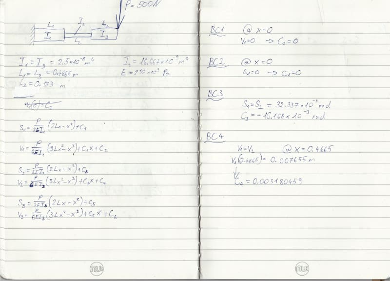
I am trying to calculate the maximum deflection of a beam that has a variable cross-section.
I have tried to follow this method:
However, my beam consists of 3 sections. Therefore, I extended the method shown in the article.
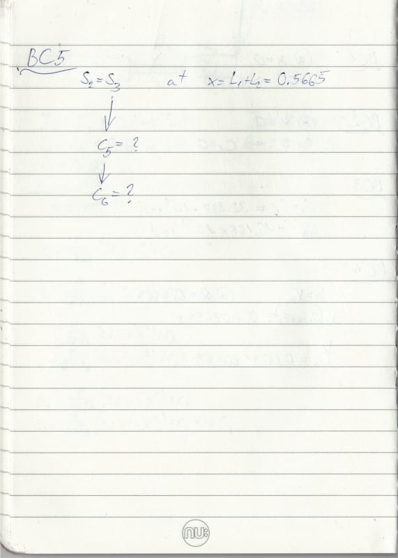
I can't seem to get right the last equation for this problem.
I have plotted my first two equations in MATLAB and they seem to give sensible results (aligned with FEA results).

Can someone check if I am using the right approach, please?
IMG_20200518_0001_ujg7cd.jpg

IMG_20200518_0002_pd4dbr.jpg
 
Replies continue below

Recommended for you

Forget about the numbers. You are showing a cantilever with point load at the tip.
The moment is P.x where x is the distance from P. Mmax = P.L where L = L1+L2+L3.
Draw the M diagram (a straight line sloping from PL down to 0.

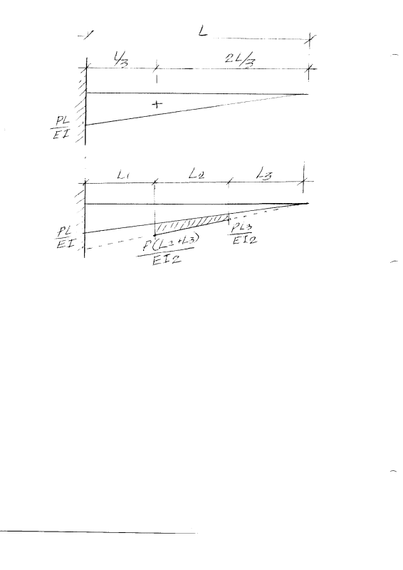
If the beam had only one value of I, the slope at the end would be the area under the M/EI diagram, namely PL*L/2EI with c.g. located at L/3 from the fixed end, or 2L/3 from the load P.

The deflection would be that area times 2L/3 or PL3/3EI (check it in your steel handbook).

Scan_20200518_kcajyf.png


If the beam has three different values of I, the M/EI diagram must be modified accordingly. Since I1=I3, let's call it I. I2 is equal to 0.666I. And 1/I2 = 1.5/I

So the deflection at P is PL3/3EI plus the shaded area time the distance from its c.g. to P (a little more than L3+L2/2). I will leave the number crunching to you.

BA
 
That sketch is a little hard to read. Here it is again.
The upper sketch assumes uniform I throughout.
The lower sketch shows the change as a result of a lower value of I2. The ordinates at each end of L2 are 50% greater than the ordinates of the upper diagram. Deflection will be the same as that of the constant I plus shaded area times distance from its c.g. to concentrated load P.

CantileverDeflection_r29zqu.png


BA
 
I appreciate there are many ways to calc the problem. I'd use integration …

slope and deflection at 0 = 0
and slope and deflection at the two interfaces from the two equations is the same s1(x1) = s2(x1), v1(x1) = v2(x1) … seems to be what you have
then s2(x1+x2) = s3(x1+x2) should give you C5 (the same way you calc'd C3), and v2(x1+x2) = v3(x1+x2) should give you C6.

Graphical methods work too.

Is this for school ?

another day in paradise, or is paradise one day closer ?
 
Hello Everyone,

Thank you for your help. Your posts are very useful.
I have managed to work out yesterday using the integration method. It turned out there was a typo in my MATLAB code... Rocky mistake, I know...

Yes, it is for an assignment.

Thanks again guys!
 
Status
Not open for further replies.

Part and Inventory Search

Sponsor