Continue to Site

Eng-Tips is the largest engineering community on the Internet

Intelligent Work Forums for Engineering Professionals

  • Congratulations cowski on being selected by the Eng-Tips community for having the most helpful posts in the forums last week. Way to Go!

Deflection of Slab with step 1

Status
Not open for further replies.

SteynvW

Civil/Environmental
Feb 1, 2016
108
Hi all

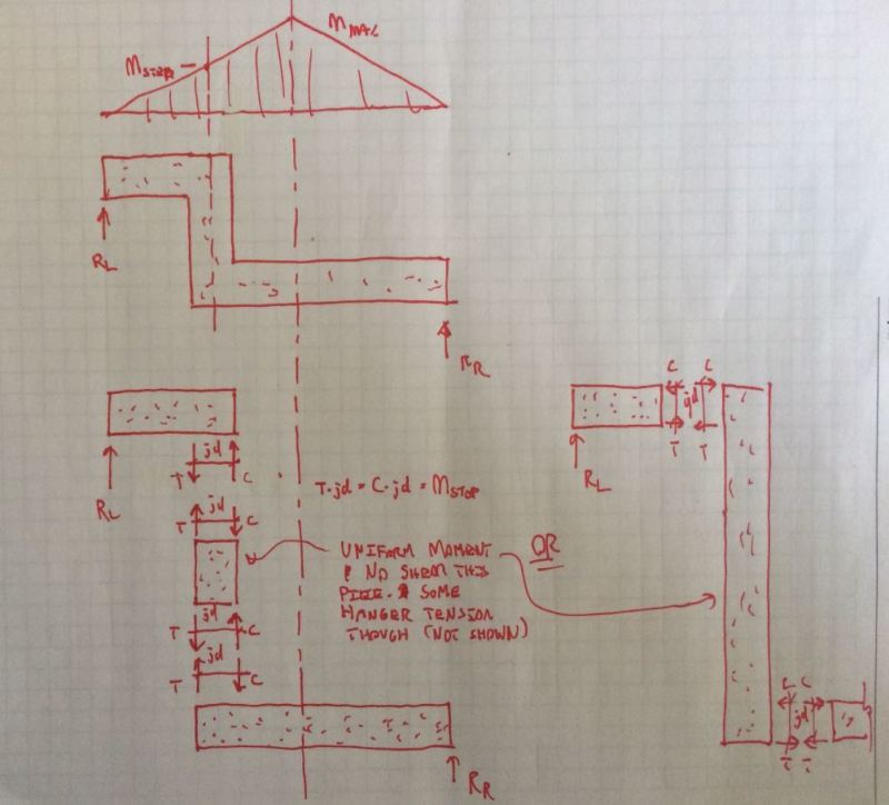
Me and a couple of engineering friends were arguing about the deflection
of a slab with a step in it compared to one without a step. (See attached sketch).

My gut feeling is that it will create extra stiffness and reduce the deflection if
it has a step. I will however never take this into consideration if I designed such a
slab.

What are your thoughts?
 
 http://files.engineering.com/getfile.aspx?folder=31bb6f32-6deb-468f-bd59-770ef63213dd&file=SKMBT_C28016052014150.pdf
Replies continue below

Recommended for you

I will vote towards no change - and might tend towards increased deflection, assuming that this is truly a one way system and there are no adjacent supports to cause this step to act like a beam.

Deflection is a function of the moment of inertia. You're increasing the depth of the slab, and therefore the moment of inertia, over a very small width and I think that this would be negligible in the deflection calculations.

Because I`m assuming this is concrete, I lean towards increased deflection because of development issues for the bars going around the corners and cracking at the corners.
In practice, I've never relied on a step like this because of these concerns.
 
Actually, it's the other way around. If the same section is maintained throughout the slab, the step adds length to the system with little to no gain in stiffness, so the deflection at mid-span increases. The resulting system is similar to (although not exactly the same) a slab with the total unfolded length loaded only on the side spans.

Try to run a few models in your analysis software and you'll see the difference. The best way to think of it is to reduce it to an absurdly large step and you'll see the deformation of that intermediate element.
 
Damn it! Once and avscorreia beat me to the juicy recommendations. I don't have much to add so I'll stick with just elaborating on the points already made. Why bother? Because a) slab step analysis is kind of pet project of mine and b) I can't really help myself for some reason.

1) Sketch A illustrates avscorreia's "extended length" concept. A lot of designers fail to capture this in the design of tall steps essentially because a) they don't recognized the issue and b) it's a tough/impossible thing to model directly in most of the common slab design software packages.

2) Sketch B illustrates Once's anchorage slip/softening concept (I think) using a strut and tie presentation which is how I've been thinking about this. In particular, the loss of efficiency in the upper, opening corner joint tends to introduce flexibility to the joint.

3) As an aside, I've previously attempted to assess slab steps for moment capacity using the strut and tie model shown below. I've found that the width of the slab step will generally need to be about twice the thickness of the slab coming into the opening joint. Interestingly, this nicely matches the standard details of many firms that show it just that way.

Capture07_jzsyfc.png

Capture08_nolvjg.png


I like to debate structural engineering theory -- a lot. If I challenge you on something, know that I'm doing so because I respect your opinion enough to either change it or adopt it.
 
Damn it! Your sketches are just too good!
(On a side note, I confess that I'm guilty of, before posting, running a couple of tests in SAP2000 just to be sure...)

I also try to use the 2h rule of thumb for proportioning the step width, combined with generous lengths for tie anchorage.
 
Agree that it should result in more deflection, of course this assumes no restraint at the ends so in reality somewhere short of this.

I've wasted a lot of time staring at these. I think it's very difficult to generalize. It depends on the height of step relative to the slab t but also where the step occurs. Is the step between supports to it's like a beam and slab is in neg bending or reverse? Or does it travel through both conditions? I've mostly resorted to trying to move them to supports and then specifying the remaining area to be filled after. Although in practice I haven't heard of any problems so like most things it seems to sort itself out.

Seems that the s&t may be complicated as well. Kootk - that st implies no horizontal shear across the joint, i.e. you could build this in pin truss? I don't think that's true unless you're exactly midspan uniform load. Maybe I'm wrong, would have to stare at it longer.
 
avscorreia said:
Damn it! Your sketches are just too good!

Yeah, nothing says "middle management bores the snot out of me" like a quality, mid-day, tri-colour eng-tips sketch.

bookowski said:
I've mostly resorted to trying to move them to supports and then specifying the remaining area to be filled after.

Interesting. I've actually gone the opposite way.

For modest steps, I'll move the step as close to mid-span as possible. I don't like having to run two-way column top steel through the steps. The bars there are dense and often large making for difficult moment transfer through the joint. Additionally, I question the validity of punching shear provisions where a slab step is involved. I figure that, at mid-span positive moment locations, the bars are usually nice and small and the moment distribution across the design strip is relatively uniform. This makes for easier joint design.

If a step is so tall that it becomes a stiff beam essentially providing one-way support to the adjacent slab, then I will try to move the step to the supports. But, then, I probably won't also have concentrated top steel over the columns.

Bookowski said:
Kootk - that st implies no horizontal shear across the joint.

Yes! That's exactly right and a keen observation. It's a neat feature of the steps that throws me a little every time that I consider it. For a step of a meaningful height, I believe that there truly is no shear transverse to the leg of the concrete forming the step. This conclusion is also supported by the moment diagram that I provided above. By definition, where moment is constant, there is no shear...

Bookowski said:
I don't think that's true unless you're exactly midspan uniform load.

The trick, I believe, is to recognize that vertical shear can still be transferred across the joint. It just presents itself as longitudinal shear in the vertical leg of the step rather than transverse shear. In that respect, it's actually a better mechanism of vertical shear transfer as it's both stiffer and stronger. It's also easily accommodated by the strut and tie model.

I like to debate structural engineering theory -- a lot. If I challenge you on something, know that I'm doing so because I respect your opinion enough to either change it or adopt it.
 
Feel like i'm being baited here and you've got this down but I'll bite. Maybe it goes back to my statement about assuming that this can unfold when in reality it can't (or can't much). If nothing else aren't you developing axial force from the unfolding/different elevations which in turn needs to be resolved as horizontal shear through that joint. Maybe not.... seems like it staring at that diagram to me, maybe not if you're at midspan.
 
book said:
If nothing else aren't you developing axial force from the unfolding/different elevations which in turn needs to be resolved as horizontal shear through that joint.

I don't see it for conventionally considered slab loads. Any chance the non-STM presentations below swing you around to my way of thinking?

To the extent that any membrane forces would develop in the slab (shrinkage/caternary), those would definitely produce high shear stresses across a step. Interestingly, if the step failed in shear it may well still function in bending and, consequently, remain able to satisfy the original design intent.

capture_uqloza.jpg


I like to debate structural engineering theory -- a lot. If I challenge you on something, know that I'm doing so because I respect your opinion enough to either change it or adopt it.
 
Makes sense and that implies that the detailing/width of step is only dependent on development of bars/opening corner stuff, doesn't depend on height of step or slab thickness etc. So expanding on the op what is the best detailing here, are you detailing the step portion like a beam with closed ties and your slab bars like a corner joint?

Still wondering if that moment diagram depends on a roller at one end though. If you have restraint from the diaphragm, so a restrained x translation (or spring) it seems like that diagram is no longer valid.
 
bookowski said:
Still wondering if that moment diagram depends on a roller at one end though.

Absolutely it does. With restraint, you get those membrane forces that I mentioned above. Membrane forces presenting as axial slab loads beyond the step would present as shear and flexure -- perhaps self limiting -- across the step. I've really been sticking to the small deformation assumptions that we normally apply in slab design.

bookowski said:
So expanding on the op what is the best detailing here, are you detailing the step portion like a beam with closed ties and your slab bars like a corner joint?

I've got a great wishy-washy answer prepared for you. I expect that you'll find it wholly unsatisfying.

1) Regardless of the detailing employed, which may involve closed ties, my intent is always to create opening and closing corner joints. There's really no such thing as torsion in the step in the general "slab fold" case. Just flexure and shear transfer. If I go closed ties, I'll try to go with lapped U-bars for constructability.

2) The typical details used by my firm, and many others it seems, have some technical detailing deficiencies in my opinion. It's usually a combination of Z-bars with several of the hooks facing the mechanically disadvantageous way.

3) Often, I'm creating a detail that's meant to deal with both sagging and hogging moments. That muddies the detailing waters a bit at often is what gets me back to something that looks like closed ties / torsion even thought that's not my real intent.

As a retirement project, I'd very much like to author an article on this (structuremag etc). With some of the advances that have been made in STM, and the utter free-ness of spreadsheet computing power, it seems to me that we could very easily be designing these things instead of just "detailing" them.


I like to debate structural engineering theory -- a lot. If I challenge you on something, know that I'm doing so because I respect your opinion enough to either change it or adopt it.
 
Kootk said:
I've really been sticking to the small deformation assumptions that we normally apply in slab design.

This implies that I'm referring to non-linear analysis. In typical slab (or beam) design a roller or pin doesn't change the result as long as you looking at analysis in the undeformed configuration, i.e. 1st order. In this case you would get a different result with pin vs roller even with small deformation/undeformed analysis. I wasn't referring to any 2nd order catenary affect, just a straight statics analysis will give you axial. I haven't run any numbers and it's probably small, and this isn't really a truss so i'm sure the concrete is more than sufficient for that axial as shear.

Regardless of the detailing employed, which may involve closed ties, my intent is always to create opening and closing corner joints. There's really no such thing as torsion in the step in the general "slab fold" case. Just flexure and shear transfer. If I go closed ties, I'll try to go with lapped U-bars for constructability.

I didn't mean to imply torsion, just ties to simplify bending bars/construction. My typical detail is the same as yours (and everyone's) but on two recent jobs the detailer ignored the detail and provided closed ties, presumably because it's easier and he hoped I would ok it (which I did).

As a retirement project, I'd very much like to author an article on this (structuremag etc). With some of the advances that have been made in STM, and the utter free-ness of spreadsheet computing power, it seems to me that we could very easily be designing these things instead of just "detailing" them.

You could publish this in structuremag now, those articles are not very technical and they are very eager for articles. Off topic but I don't really understand that magazine - it's not technical enough to be very useful to engineers but it can't be a great marketing tool since the readership but must be entirely engineers.
 
bookowski said:
Off topic but I don't really understand that magazine - it's not technical enough to be very useful to engineers but it can't be a great marketing tool since the readership but must be entirely engineers.

If your target market is Engineers like structural analysis software or new structural products then it's a perfect valid marketing tool.
 
Just did a quick risa test, 12"x8" concrete strip with 200 plf loading and horizontal restraint. I don't see why you'd assume a roller for something like this. This is still small deformation/undeformed/1st order. Moment diagram is very different, but the shear is still small stuff.
 
 http://files.engineering.com/getfile.aspx?folder=c9fdfbd3-5c98-4fdf-9b8a-5055c9fc5d4a&file=quickStep.png
Book said:
This is still small deformation/undeformed/1st order.

My choice of words was poor when I mentioned "small deformation". It was never my intent to imply that second order / non-linear analyses would be required for the axial loads to present themselves. Rather than "sticking to small deformation", it would have been more accurate of me to have simply said "sticking to ignoring membrane effects". Although even that gets murky with a step in play as membrane effects become primary/normal effects across the step. Anyhow, my bad.

Book said:
I don't see why you'd assume a roller for something like this.

For me, it would depend on the purpose of analysis:

1) For something like the OP's hypothetical test case -- an isolated simple span -- assuming pin-roller makes sense to me.

2) For evaluating the demands on the step, assuming pin-roller no longer makes sense to me as a result of your insights here. Most slabs will experience membrane forces as a result of the incidental restraint provided by shear walls, adjacent framing etc.

3) For slab flexural and shear design in general, I would definitely not want to assume pin-pin support. The membrane load path is difficult to assess in my opinion so I wouldn't want it entering into the load carrying capacity determination for conventional slab designs.

4) In my experience, most slab steps are not explicitly modeled when FEM is used. Rather, the slabs are analyzed/designed as though the steps were non-existent and then, at a later stage, the steps are "detailed". In this process, I don't think that it would make sense to attempt to model slab axial restraint since, in a slab modeled as though it were flat, membrane action isn't going to generate the interesting results at the slab step anyhow. This is, of course, more a commentary on how things are rather than how they ought to be.

leftwow said:
I tried to model this in staad using w sections. Seems the vertical beam is tension on one side and compression on another

Book said:
Moment diagram is very different, but the shear is still small stuff.

These are interesting results. Kudos for taking the time to generate them. The difference in the moment diagrams is surprising to me. Apparently, you possess an intuition for the situation that I lack. I`ll try to find some time on the weekend to run a couple of studies myself. In the interest of keeping things simple and easily reproducible for anyone who may be following along, I think that I`ll do it like this:

- Steel.
- Weightless structure
- Point load applied at step
- Step at span 1/3 point
- Step height equal to 1/4 span

I may also tinker with changing the pin supports to springs to model some flexibility. I'm wondering if this might one of those situations where the effect is highly sensitive to the difference between full fixity and partial fixity. If anyone has recommendations regarding logical support spring constants, I'd welcome the advice.


I like to debate structural engineering theory -- a lot. If I challenge you on something, know that I'm doing so because I respect your opinion enough to either change it or adopt it.
 
I'm in the not modeled but detailed camp as you noted most are. I've tried to poke at this before but always come back to this route since it seems to work and fits in with software limitations. I have fiddled with safe of changing the datum on each side and doing a thickened slab but I don't think it understands it beyond a thick area. I see that Rapt software says 'vertical steps in horizontal surfaces' under technical features on its web page, similar language for Adapt. Haven't used either so not sure if that goes beyond the safe type treatment.
 
I did a couple of FEA on STRAP. (See attached)
With a pinned end on one end and a roller on the other.

Although there is a difference, it rarely differs more than 10%.
It actually makes sense now that we ignore the step when designing slabs.
 
 http://files.engineering.com/getfile.aspx?folder=dde6cfb7-d6af-419d-b892-6744ad1a0f49&file=Strap.pdf
Status
Not open for further replies.

Part and Inventory Search

Sponsor