Continue to Site

Eng-Tips is the largest engineering community on the Internet

Intelligent Work Forums for Engineering Professionals

  • Congratulations MintJulep on being selected by the Eng-Tips community for having the most helpful posts in the forums last week. Way to Go!

Derating of IEC 62271-100 HV Breakers

Status
Not open for further replies.

cherryg222

Electrical
Apr 6, 2016
23
How may of you have actively derated breakers from their test certificate (IEC 62271-100 HV breakers)which are tested at standard time constant of 45 ms? What method did you employ? Did any of you use the CIGRE Technical Brochure No.304 OR the ENA Engineering Recommendation G89 (2011)? If you have used any other innovative methods, please elucidate.
 
Replies continue below

Recommended for you

I can see on these curves for an X/R ratio of 17 and standard 45 ms curve, about 70% de-rating is applicable. Shouldn't that be 100% for standard calculation?
 
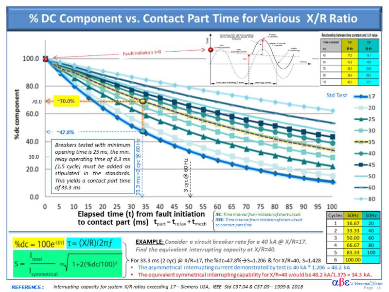
To follow the original post and to respond Power0020 question, below is re-edited graphical illustration
of % DC Component vs. contact parting Time for Various X/R ratios.

At difference than the previous graph, the horizontal axis is the "Elapsed time (t) from fault initiation of the breaker contact part in ms (sum of the operating time of the breaker and relay)

This illustration includes an example of a circuit breaker rated for a symmetrical interrupting current of 40 kA (although not explicit in the nameplate, it is understood that this rating is a standard X/R=17 equivalent to a time constant of τ = 45 ms and asymmetrical current of 48.2 kA).

The breaker short circuit breaking capacity was derated from 40kA to 34.3kA (14.32%) to operate in a system with X/R= 35 equivalent time constant τ=93 [highlight #FCE94F][ τ = (X/R)/ 2Π.f][/highlight]

Notice that the total parting time is the sum of the breaker tested minimum opening time plus the minimum relay operating time [highlight #FCE94F](ttotal = tBkr Mech + tRelay)[/highlight]. Modern SF6 Bkrs often tBkr Mech= 25 ms and relay min. operating time of 8.3 ms (1.5 cycles). Safety margin is usually recommended around 20% should be added.
Breaker_Derating_Factor_for_time_constant_vs_X_over_R_hwiird.jpg
 
cuky2000..Thanks for providing the graphical derating factor chart. I had a question. The derating factor is definitely taking care of the asymmetrical current. Does it take care of the energy carried by the parting contacts also? CIGRE Tech Brochure 304 says: The arc energy represented by the area of the major loop of current is probably one of the most important considerations. In other words, the arcing energy (equivalent to the integral of current) shall not be higher than that tested.
 
Hi Cherryg222,

Regarding your question: The short answer is yes. The arc energy carried by the parting contacts is also take in consideration during the test of the circuit breaker.

The IEC Std. 62271-100 establish the most likely time for interruption scenarios and not only includes the minimum clearing time (relay + breaker+ arcing) but also the next full major current loop found, the earliest full major loop or extended major current loop that the circuit-breaker can see in service.

There are two acceptable methods by the standards to account for the arc energy during the testing of the CB:
Exact method: Compare the integral of the current waveshape from contact separation to current.
Alternate Method: Compare the parameters of the last current loop (Ipeak, loop duration and product [highlight #FCE94F]("I × t")[/highlight].

BACKGROUND: The Standards recognize the importance of the consideration of the arc energy since some circuit-breaker technologies (ex. puffer design) use the arc energy as the main source of energy for the current interruption. "For such technologies, lower arc energy may result in longer arcing times and the ability to interrupt lower current should be carefully evaluated. Care should be exercised in the evaluation of the minimum arcing time. The arc energy associated with minor current loops is lower for higher d.c. time constants which may result in a longer minimum arcing time and thus in a longer maximum and medium arcing times".
 
Just to add to this post. The exercise of determining a derating factor actually got changed to determining if a certain breaker with a test certificate (T100a and three different time constants; 45ms, 90ms and 135ms) is suitable to the system condition.
Was successful in generating the actual decaying sinusoidal curve, and determine the separate amplitudes for the 1st, 2nd, 3rd ....major loops and also their durations. This can then be used to compare the tested breaker data (energy through the last major loop) with that of the simulated results based on system data. The only variables are the Isc rms and the time constant (or X/R ratio). The tricky part is selecting the correct loop for comparison, which can only be done with help of the manufacturer and the correct interpretation of the test certificate.
 
Status
Not open for further replies.

Part and Inventory Search

Sponsor