Continue to Site

Eng-Tips is the largest engineering community on the Internet

Intelligent Work Forums for Engineering Professionals

  • Congratulations IDS on being selected by the Eng-Tips community for having the most helpful posts in the forums last week. Way to Go!

Design of a vessel head with a filleted rectangular door nozzle

Status
Not open for further replies.

Amr Mohamed

Mechanical
Oct 3, 2021
5
Dears;
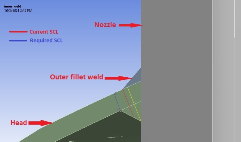
I am designing a pressure vessel as per ASME Div.1 Edition 2019, the client requested that the vessel has a rectangular nozzle with filleted corners, and a flat door to close it against a rubber air tight gasket, during the entire vessel design phase I haven't faced any problems except when I started designing the head and that hugely large, weirdly shaped opening, a detailed analysis of the door, door frame and adjacent shell is required which after further research, I found out that using design by analysis rules of div 2 (as indicated by Mandatory Appendix 46). I created a 3d Model for the head and the doorway to perform the FEA on. According to div 2 rules the stress classification line should be perpendicular to both the inner and outer surfaces of the head (aligned radially) however, the line starting at the toe of the inner fillet weld joining the nozzle and the head and ending at the outer weld's toe is not perpendicular to the two surfaces, as both welds have the same size; and according to ASME PTB 3 2013 there should be a stress classification line at the toe of the weld. the only way I see is to make them of different (and probably bizarre) sizes so the points create a radial Stress classification line which I can use to find linearized stress results. Am I over thinking this? is it ok if the stress classification line is not exactly radial? is there anything I am missing? I am actually in need of any help to find out whether I have been doing right with this project or not.

Thanks for your time to read this, any help whether by a reference, an old thread or an opinion would be very appreciated.
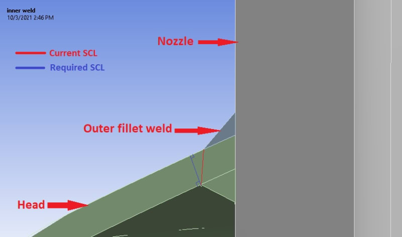
SCL-Post_nrkohq.jpg
 
Replies continue below

Recommended for you

If this is such a large opening (like a doorway) that the opening takes up the whole crown of the head and encroaches close to the knuckle then I would question if the Elastic Stress Classification method is suitible. The stresses in the head at the corner of the opening are of concern.
I would do two lines.
The blue line is correct.
The red line should be perpendicular and run through the weld. It will provide an approximate result which will require judgement to interpret. It's the blue line that will be the basis of the result.
But I suspect that the corners your door geometry will require an Elastic Plastic Analysis.
 
Thank you for your kind & quick response,

What exactly do you mean by "run through the weld"? do you mean like the red or the yellow lines in the attached photo? or do you mean something else?
SCL-Post_uy3bxg.jpg


The toe of the fillet weld at the door's corner does not intrude in the knuckle but it's some what close to the knuckle edge about 75 mm (3 inches). however, the head thickness is 16 mm that makes the 75 mm distance about 5 times the thickness and given that the pressure is relatively small (4.5 bars). an initial run showed that the stresses around the corner are high but decay before reaching the knuckle region. so I thought it might be acceptable to perform an Elastic Stress Classification method. still I am not quite sure as to the validity of this line of thought.

the head is 2400mm ID with a 2400mm crown and 240mm knuckle
 
Like the red line but that just looks odd. Perhaps also try the red line but not through the weld. I think the mathematical linearisation integration in ANSY will spit out garbage for the red line. You will need to informally linearise with your own judgement and plenty of additional margin. Perhaps by inspection you will find that the bending stress at the top of the red line is less than the blue line.
The blue line is correct.
Perhaps your stress distribution line will be squiggly rubbish making this an Elastic Plastic Job.
There will be an immense amount of bending at the door corner, of which some will be secondary stress but is also partially Primary as well. How do you handle this? Do you somehow separate them or assume all is primary?
With this massive odd-shaped object in the middle of the head causing inconsistent stress distributions in the knuckle, have you considered localised buckling of the knuckle?

I did your exact project 15 years ago before I knew anything about stress classification. The 3rd party appraiser (the most respected in England) just looked at the drawing of my chuncky overdesigned manway and said "that'll do the job" without even reading the analysis report.
 
Can you tell us more info?; design pressure & temp, dimensions, materials.
Is this nozzle on vertical vessel?

Regards
 
Unless it is hinged and intended for human entry, please don't call it a door. It's a cover.

A little OT maybe, but a pet peeve of mine :)

Regards,

Mike

The problem with sloppy work is that the supply FAR EXCEEDS the demand
 
I assume this is a vertical PV and the nozzle is on the top head (not reported by (OP)). Therefore, the nozzle must be flush with the inside of the head to avoid entrapment of air during hydrostatic pressure testing.

Regards
 
The door is sealed by internal pressure pushing it up against a rubber seal (like an O-Ring), therefore low temperature.
The dimensions and pressure indicate a horizontal hyperbaric chamber with a doorway for commercial divers to enter.
Or perhaps an Oxygen treatment chamber for the treatment of sports injuries or other ailments.
 
@drivemenuts

I also think that red line looks weird and will definitely consider not running it through the weld. I just think that technically any nozzle in a formed head that has an inside projection and welded on both sides should -especially if it's a hill side nozzle- face the same issue (with varying degrees depending on the head thickness, weld size and location of the nozzle in the head) in determining the orientation of the SCL and just want to know what others will typically do in such a situation. do they just connect the weld toes? Is there a certain tolerance limit to how correct the SCL should be oriented?

I agree that there will be a lot of bending in the corners but I don't understand why it's partially primary stress? I thought it will be mainly secondary stress according to table 5.6.
To be honest I have not thought of localized buckling in the knuckle since the head itself has 50% more thickness than that required by the rules for the pressure (div. 1 rules which are even more conservative) and because an initial run showed that the stress concentration around the corner quickly decays before reaching the knuckle region though I admit that the stress distribution in the knuckle is still a bit weird around the corners. Do you still think that a localized buckling analysis for the knuckle is still required?

An elastic plastic analysis is currently not possible due to computational costs and because I don't have much experience in stress classification to begin with, which is why I tried to leave plenty of margin in the design and try to do as "proper" an analysis as I can with all the possible guidance that I can find and now kind of hoping to repeat your situation 15 years ago.

It is a hyperbaric chamber for oxygen treatment. I am kind of curious was that project from 15 years also a PVHO-1 vessel? so far this is the only application I have encountered that requires a rectangular door and you seem very familiar with the concept.

Thank you very much for your replies and support.
 
@r6155
Sorry for the late reply I got caught up in something.
It's a horizontal vessel intended for oxygen treatment as @DriveMeNuts have mentioned. I mentioned most of the design inputs in a previous reply but I can sum them up for you.
Design conditions: 4.5 bars @90°C
Material: SA-516 gr. 70
Head dimensions: 2400 ID, 2400 CR, 240 KR, 16 mm thk
Opening dimensions: 1700x860 mm with 100 mm fillets

Thank you for the note regarding top nozzles and air entrapment I will definitely keep that in mind.
 
@SnTman
It is hinged and it is intended for human entrance so I think it does qualify as a door.
 
It was for Orkney Hyperbaric Trust, Scotland. The vessel is designed to PD 5500 while using PVHO-1 for the design of the viewports and internal head weld. The result is similar to what you would get for an ASME VIII Div 2 PVHO-1 vessel.
The link below has some images.
It's a triple lock with one end for commercial diving and one end for the National Health Service, and a central entry lock.
Orkney Hyperbaric Trust
 
Amr Mohamed, agreed :)

The problem with sloppy work is that the supply FAR EXCEEDS the demand
 
Status
Not open for further replies.

Part and Inventory Search

Sponsor