Continue to Site

Eng-Tips is the largest engineering community on the Internet

Intelligent Work Forums for Engineering Professionals

  • Congratulations SSS148 on being selected by the Eng-Tips community for having the most helpful posts in the forums last week. Way to Go!

Design of connected foundations for lattice towers

Status
Not open for further replies.

Fontain

Structural
Aug 7, 2015
5
Hi
I recently received a request to perform a modification design for a telecommunication tower foundation. It's a four leg, 80m tower and
the base reactions from the tower analysis are:
1914.61 kN Max compression
1665.27 kN Max uplift
27821.77 kNm over turning moment
756.12 kN Base shear
574.36 kN Tower and appurtenance weight.
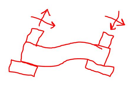
Currently the tower has isolated footings beneath each leg (please see sketch attached) and these fail massively in uplift. Unfortunately the tower site has a number of constraints both within and outside the fence that make simple expanding the foundation impossible. I am hoping to counteract the uplift by connecting the foundations using a beam. IEEE standard 691 mentions this as a viable method to increase the capacity of tower foundations, I checked the web and apparently it is also approved by Korean standard DS 1110. Unfortunately, I haven't come across a reference that gives specific guidance on how to analyze/design such a system. Is there any guidance you can give in this regard and perhaps any references you can point me to?

Thanks in advance
 
 https://files.engineering.com/getfile.aspx?folder=4535e51e-8c15-4ee6-8f5a-1997181c8e96&file=Foundation_sketch.pdf
Replies continue below

Recommended for you

I would go for tension piles.

I have not come across the idea of using a beam in this manner but I don’t instinctively like it I must say. What are the principles behind its design? Are you hoping to cantilever a beam from the downward leg to resist the upward leg? How would this be resolved? Inherently I feel that you would still have an overall stability issue in that the base is simply not heavy enough.
 
Thanks for the quick reply MIStructE IRE

Obviously it isn't a method that is commonly used, but as I stated, it is mentioned in some engineering codes primarily IEEE 691 which I happen to posses. From what I have read, the idea is that the beam will transfer a downward force to the upward leg due to it's own weight and the weight of the soil around it. So in regard to the uplift force it simply acts as a counter weight. Here are the issues, that have got me confused:

Firstly, just like you, I thought that the beam should be designed as a cantilever supported at the downward leg and resisting the uplift force but according to the documents I read, it should be checked for two conditions, fixed on both ends and then fixed on one end and pinned on the other. For the fixed-fixed case, this would suggest that there are certain moments about the end of the beam, but where do they come from? The beam isn't directly loaded by the tower base reactions and it isn't suspended so it's own weight shouldn't be an issue. The only force I can think of that can cause these moments in the tower base shear.

Secondly, since we will be tying everything together, shouldn't the system created be able to counter the overturning moment? I'm of the view that since all the individual footings will no longer act in isolation, the system should act like a pseudo mat foundation and resist the OTM but no mention is made of this.

Lastly, they state that the beam should be stiff enough to resist rotation between the footings it connects but no mention is made of how to go about designing for this condition.

I have looked all over but can't find any more information on the subject.

I regard to your suggestion, I had already suggested the use of piles to the client but I suppose they want to check all other options first. I believe the tower is located somewhere in Eastern Africa and the equipment required for piles isn't readily available. But perhaps I can pick your mind, here's what you don't know, there are so many existing structures around the tower site and close enough to it that expanding the foundation outwards isn't an option, within the tower site, there are a number of equipment slabs that the client doesn't want to touch directly under the tower so we can't really head in that direction either. With that in mind, if this job were handed to you and piles were not an option, what would you do?
 
What is the soil like in Eastern Africa? I think that might also dictate your best solution.
What is the status of the tower during construction? Is it to stay in position, being upgraded, or being dismantled for a new one in place? That may also dictate your situation.
And how was the tower foundation originally designed? Curious, because that's a huge tower and huge loads. But the footings look rather small but deep.

If uplift is a concern you either need to (a) tie it down or (b) make the four footings act together or (c) adjust the tower base design to accomodate a solution. I won't solve this problem but I think I would try to rationalize out connecting all four footings with a same thickness mat. Insert dowels to transfer the forces to the mat. That might provide enough dead weight to resist and enough continuity to transfer/share the load.
 
Fontain said:
I am hoping to counteract the uplift by connecting the foundations using a beam. IEEE standard 691 mentions this as a viable method to increase the capacity of tower foundations...

...if this job were handed to you and piles were not an option, what would you do?

Connecting beams will increase foundation capacity, but not in a way that will help with this project. Connecting beams are typically used for electrical transmission towers in poor soil (e.g. swamps & marshes) where the soil does not provide sufficient lateral support for independent leg foundations. Connecting beams make a stable structure out of the individual leg foundations.

Connecting_Beams-600_bvthyt.png


Get a geotech engineer on the project. With the constraints requested by the client, believe you will need "backup" to convince the client that relaxing some the constraints will almost certainly be required to reach a practical solution.

[idea]
 
OP said:
I'm of the view that since all the individual footings will no longer act in isolation, the system should act like a pseudo mat foundation

I see it the same.

OP said:
For the fixed-fixed case, this would suggest that there are certain moments about the end of the beam, but where do they come from? ... The only force I can think of that can cause these moments in the tower base shear.

I agree with your base shear assumption and see it as shown below.

OP said:
Lastly, they state that the beam should be stiff enough to resist rotation between the footings it connects but no mention is made of how to go about designing for this condition.

Also per the model below I think. When all is said and done, you'd like the bearing pressures under each of the footings to be fairly uniform.

I have know idea if this mechanism addresses your OT demand but I'm fairly certain that it is the model intended in the literature that you've been reading.

c01_rcpou9.jpg
 
I think your model is correct Koot.

However I think there’s still an overall instability here as the base is simple not heavy enough.

How you approach this depends on whether or not it has already been built?
 
Hi all

Thanks for your input, the soil has an ultimate bearing capacity of 1709 kPa or 11899 psf so we haven't had any bearing issues.
Yes the tower has already been built and will stay in place during the foundation modification. Unfortunately as is the case for many towers I've dealt with in Africa, there are zero records. No structural drawings, no design reports, no maintenance records, no material test reports. They were either never handed over or have been lost. We often have to start from scratch and where we fail to get the required information, fill in the gaps with reasonable assumptions, usually leaning to the conservative side.

In regard to the proposed solution, like I said, it should provide so additional uplift capacity and I would still like to find out how to go about it. Information is rather scarce though. In regard to the proble at hand, I have decided to cast a single mat that incorporates all the isolated foundations. 12.5m x12.5m x 0.8m and enlarge the foundation column to 1mx1m so that I can incorporate my own steel into it. Not sure if this will fly with the client though.
 
However I think there’s still an overall instability here as the base is simple not heavy enough

I think the same, simplistically you need a lot of concrete to resist the 1665kN uplift locally to the legs, sure you don't have to provide it there, but any concrete located closer to the compression legs has more limited benefit. For the compression force to benefit the stability you need a large enough footing to start with. If the compression leg force acts beyond the centroid of the reaction on the soil then it's still destabilising the footing.

1665kN/(0.9x24kN/m^3)= 77m^3 of concrete. This is a solid block of concrete 4.25m x 4.25m x 4.25m, i.e. a lot of concrete!
 
Status
Not open for further replies.

Part and Inventory Search

Sponsor