Continue to Site

Eng-Tips is the largest engineering community on the Internet

Intelligent Work Forums for Engineering Professionals

  • Congratulations waross on being selected by the Eng-Tips community for having the most helpful posts in the forums last week. Way to Go!

Design of RC Monlithic Rectangular Water Tank

Status
Not open for further replies.

AlexYu

Civil/Environmental
Jan 11, 2016
4
Hi all, I am working on the design of a RC water tank, and I need your help...!!
Thanks in advance!!

Size and Structural Form

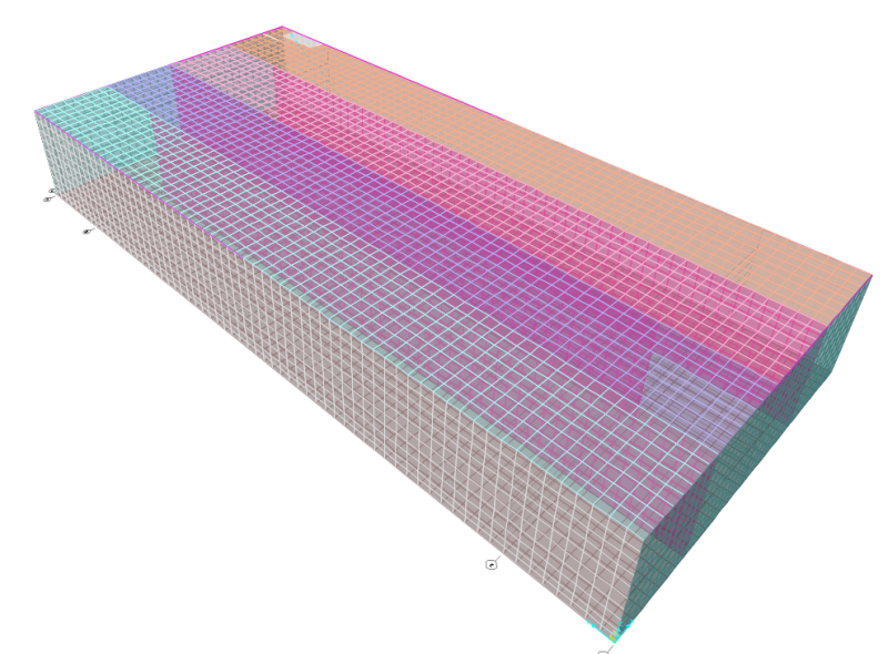
RC Rectangular Water Tank
- Designed as a Rigid Box Structure, as the Roof, Base & Walls are all monolithically connected
- Size of the Tank = 68m (Length) x 30m (Width) x 9m (Height)
- Thickness of Roof, Base, Walls = 0.4m
SR_Model_v5kxwk.png


Baffle Walls
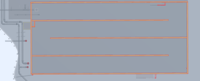
- 3 Baffle Walls inside the tank to guide the flow of water
- Designed to be Full-height Structural Wall transfering load from the Roof to the Base
- Not Full-length in order to allow water flow
Baffle_Wall_csx3jv.png


Foundation
- Shallow Foundation sitting directly on Soil
- Base Slab acts as Foundation

Questions

1. What is the structural behaviour of the tank under large lateral loading, like seismic loading?
- The analysis shows that the roof has large in-plane deformation, resulting in high tension at far side, and compression at near side.
- The behaviour is similar to a beam sagging under UDL (compression at top; tension at bottom).
- The Roof does not act as a rigid diaphragm, but a flexible one.
- I reckon it is the actual behaviour, as the roof and the walls have same thickness, yet the roof has a much longer span (68m) while the wall is just 9m tall. The in-plane stiffness of the Roof should be smaller than the Walls. Given the smaller relative stiffness, the roof is flexible.
- To be clear, I used Area Spring (z) and Soil Spring (x & y) at Base Slab in SAP2000, not sure if it affects the result???

2. Large Axial Loading in both direction on Roof
- The analysis shows that the roof has large axial loading in both lateral direction (x & y).
- The results are similar in Walls.
- Since the long size of the tank is 68m, it is designed as column, it must be slender and will fail by second order effect...
 
Replies continue below

Recommended for you

Generally, a concrete roof would be considered a rigid diaphragm, but I suppose since your diaphragm is so long, it might be flexible. However, in this case, I don't think it makes any difference, since the diaphragm is a simple span.

It does not sound correct that there is a large axial load in each direction in the roof slab. Check your boundary conditions.

DaveAtkins
 
I've one or two or a hundred of these. For one, your walls are too thin, you need about 24 inches or 30 inches of thickness. The slab needs to be thicker than the walls by at least 2 inches. The top slab needs to be about 15 inches or so for deflection. You need to fix the walls at the base and pin them at the top. This is for several reasons, including economy and ease of construction, but mostly for leak prevention. The interior walls can be thinner, but that's a long drop for concrete and vibrators. Your 15 inches seems about right.
The top slab will take some tension, but the reinforcing in it should take it as long as you use code mandated minimums. For fluid loads I wouldn't use a load factor less than 2.21 (1.3 times 1.7) if you're doing concrete to ACI.
Your wall shears and moments should closely approach a propped cantilever. If they don't, check your numbers. And the corners will need additional reinforcing, which a computer analysis should represent accurately.
I disagree with your concept of the roof acting as a 68 m column. If the baffle walls are supported by the roof slab, those forces will be collected pretty quick by the walls.
As far as soil springs and other fancy effects, the slab should have a pretty even load distribution, so I don't think they'll impact your results. But if you want to use them, they shouldn't harm anything.
 
Agree with Jed!

You will also need to consider joints, to reduce shrinkage stresses, to reduce pour sizes and possible thermal expansion.

If you need for thermal, rebar will need to be discontinuous which will change the stresses somewhat from the computer model. You will approach a propped cantilever situation, except for the corners.

If you are in a seismic zone, refer to Portland Cement Association "Design of Liquid Containing Concrete Structures for Earthquake Forces". Design for impulse and convective forces. Interior walls also! Check free board- you may need to consider uplift on roof due to sloshing. Also PCA "Rectangular Concrete Tanks" is a good, non-computer design guide.

It looks like you may be from a metric country, in which case there may be other design codes to consider.
 
"The slab needs to be thicker than the walls by at least 2 inches."
Jed:
Just curious.... why is this needed? Not disagreeing. Just not familiar with it as a requirement.
I know you say the walls will "collect that load" but what will they do with it? If there are relatively flexible (compared to the axial stiffness of the top slab), won't the top slab still act like a column?

I agree with the notion that construction joints will be a big deal.
 
This is due to the requirement that the cover for reinforcing cast against soil is 3 inches. So you've given up an inch of concrete slab for cover vs. a wall. And I make it 2 inches, just because. I actually make it 4, because I like 3/8 inch scale for my details and that's an 1/8 inch. Slab on grade concrete is very cheap.
I understand that the 68 m is the long direction. So the baffle walls act as shear walls in that direction. No need to treat the slab as an unsupported column for the whole length.
 
How are you going to get ventilation air into the far corner with only onn opening at the start/entry of the tank labyrinth path? Sure,, maintenance and inspection are not done too often, but you'll never get air flow into the end. And you can't even sample it either, even if you assume the top of the water level is "open".
 
A few more thoughts:
Snow or ice loading on the roof?
(It appears to be modeled as a simple flat slab, with no slope!)
If snow or ice is possible, then you MUST add those dead loads to the weight/m^2.

Rainwater runoff: Regardless of snow loading, you must slope the roof to prevent ponding and casting/concrete ponds on the flat surface. 2% is a "parking lot" slope, but less will still drain the roof: Cast the bottom of the roof flat - to simplify the forms, and divide the 30 meter distance into two halves: Slope the center of the 15 meter half from the center out to the edge by 1% (0.01 x 15 m = 15 cm. This will add a little weight to the center of the 3x walls.

If the roof extends about 1 inch (25 mm) past the edge of the outer wall, runoff gutters can accept the roof water runoff and divert it AWAY from the tank foundation without erosion. If the middle of the roof is highest (least amount of fill concrete, least weight solution), then two gutters would be needed down each side. Once roof runoff is collected in the gutter(s) then you can run it away from the tank foundation just like any other house r building. I'm not 100% sure anything more elaborate is needed, but you do need to be sure area runoff water from uphill of the tank is NOT trapped by the new tank walls. Water under the foundation, erosion or constant dampness under the tank MUST be avoided since this is a lot of weight on what is ultimately only the dirt under the bottom of the tanks..

Tank floor runoff.
Not discussed at all. The slope on the floor - if this is only water, not extremely dirty (like sewage or food processing waste), not toxic, and does not EVER need to be rigorously cleaned and rinsed out later - then can easiest be done by sloping the floor of EACH 7.5 meter labyrinth path width to a very shallow "V" groove on the bottom. That V groove then has a flat run to the entry portal. To drain the tank with a modest amount of water remaining on the tank floor, pump the sump pump right near the portal in a 6-12 inch deep sump pit. The V groove will accept almost all of the water from the back labyrinth of the tank, and the continuous V groove lets people safely walk down the tank near each wall.

Why a 68 meter cantilever?
Is not the roof supported at each edge by the outside wall, then a 7.5 meter span, then a wall, then a 7.5 meter span, the center wall, 7.5 m span, wall, 7.5 m span, then the outer wall. Each span is then only cantilevered 3.75 meters out, and the weight itself is balanced by the opposing weight on the other side of the center walls. The roof re-bars will be extended across each 7.5 m span from the outside walls to the other outside wall.

Pour sequence. The interior walls are obviously not watertight - only for channeling convenience. Make construction cheaper, easier. Make the outside forms and floor forms. Lay ALL outside wall reinforcement and roof ties rebars, and (obviously) the floor reinf and floor mat pads. Lay ALL center divider wall rebar ties and vertical stubs to a small height above floor grade (1-2 foot maybe, US units) .

Pour the outside walls, floor and floor drain V-slopes, and the stub dividing walls. Give it a few days to set, then pull that formwork, work on the hardening floor to set up and brace the interior walls and the roof forms on a hard, firm predictable surface. It will not be at full strength, but will be better than "open air" by a lot. Pour the roof, ventilate, then go inside the labyrinth and pull out the roof forms.
 
As others have said I would treat the roof-wall connection as pinned and design the walls for out-of-plane. Since the walls are long it would be 1-way action and you can use a foot strip. Normally shear would control so the wall thickness would be on the order of 30" at the base. Depending on the jurisdiction you're in you'll need to use ACI 350 as the concrete code. They have different factors for fluid load compared to ASCE 7 and ACI 318 and different rebar clear covers. It also includes a durability factor depending on the rebar size and normal/severe conditions. Also look at ACI 350.3 which will tell you how to determine your impulsive and convective forces (if you're in a seismic area).
 
Status
Not open for further replies.

Part and Inventory Search

Sponsor