Continue to Site

Eng-Tips is the largest engineering community on the Internet

Intelligent Work Forums for Engineering Professionals

  • Congratulations KootK on being selected by the Eng-Tips community for having the most helpful posts in the forums last week. Way to Go!

Design of shallow moment resisting foundations 3

Status
Not open for further replies.

CivilSigma

Structural
Nov 16, 2016
100
I have been reading about the design of shallow moment resistant footings using "Foundation and Anchor Design Guide For Metal Building Systems" by: Alexander Newman
The author discusses the design of the foundation to lateral loads.

Horizontal thrust onto the foundation from a column above is only used to design the foundation wall below to moment and shear (M = force * depth of wall).
However, the author does not design the footing for this moment.

Isn't the moment transferred from the foundation wall to footing below? Should it be considered in the design of the footing?
The footing is only designed for moments from net earth pressures. I find it counter intuitive that we don't design the footing from the moment coming from the wall above.

 
Replies continue below

Recommended for you

Are you having an invert T foundation that supports columns? Can you show a sketch indicating your concerns in a more clear way? I am wondering which part was left out in the design by the author.
 
I do not have a copy on hand of the referenced text, but the way I am thinking about it designing the footing for "moments from net earth pressures" does include the "moment coming from the wall above". Wall moments cause foundation rotation resulting in a soil pressure gradient under the footing. Footing is designed to resist the resulting soil pressures.

I agree that a sketch or a copy of the example in question may clear things up. These type of problems are sometimes easier to visualize by "flipping them upside down" (i.e. the soil pressure is treated as a uniform load on the footing and the wall is a fixed support.)

 
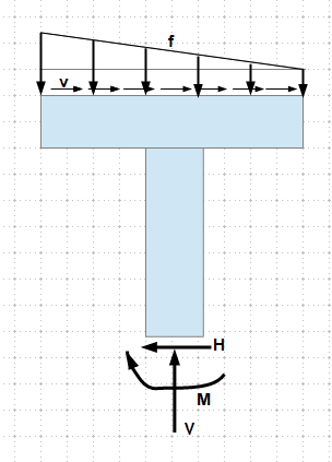
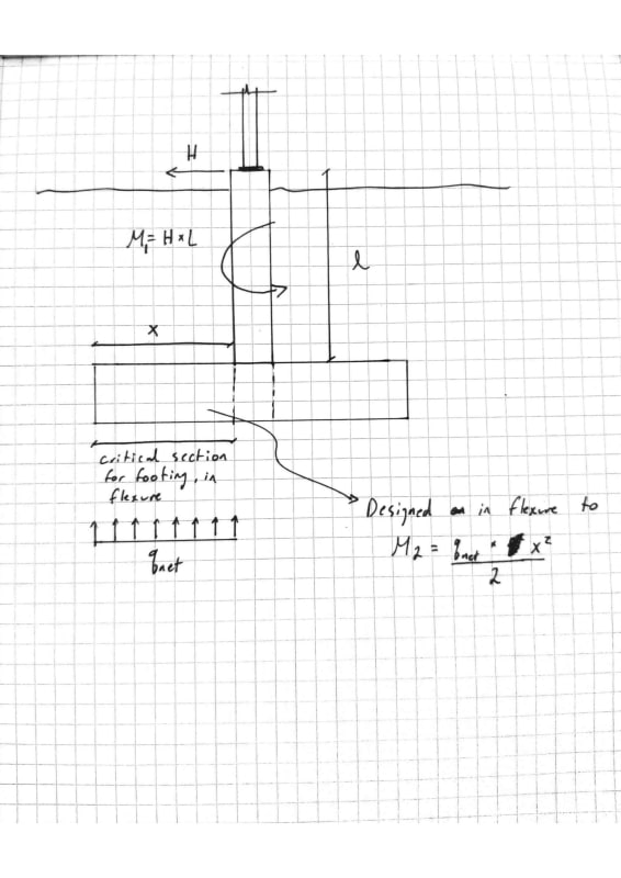
r13 and RWW0002, please see below.
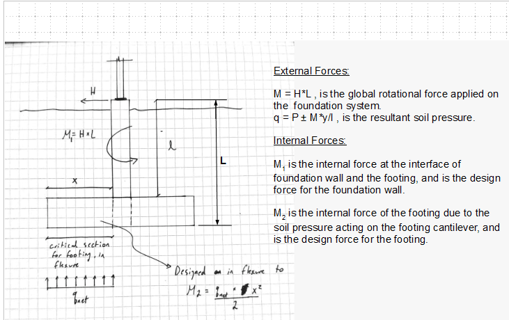
The author does not design the spread/strip footing to moment M1 in my figure.

EDIT: RWW002, now that you mention it, eccentric moments from the foundation wall will influence the soil pressure distribution under the footing. Is that how we "capture" moment M1 in the flexural design of the footing?

0001_kclxiy.jpg
 
I think what RWW0002 describes is what the author does. He gets the soil pressure with the thrust force in the "Proportion the Foundation" section then uses that to design the base.
 
I have been reading about the design of shallow moment resistant footings using "Foundation and Anchor Design Guide For Metal Building Systems" by: Alexander Newman
The author discusses the design of the foundation to lateral loads.

Horizontal thrust onto the foundation from a column above is only used to design the foundation wall below to moment and shear (M = force * depth of wall).
However, the author does not design the footing for this moment.

I have that reference and he typically takes out the horizontal thrust with things like hairpins, tie rods (or whatever) so the bottom of the footing doesn't see the moment.

But taking care of the moment is a straightforward calc. (If needed.)
 
WARose,

I am reading chapter 7, and section 7.5.2 address the effect of the eccentricity moment by adjusting the soil stress distribution.
I also went through example 7.1, the author only considers the modified soil stress distribution in computing the design moment in the footing.

I understand now that the effect of moment is captured by the modified soil stress distribution.
But can't we explicitly add the moment from the wall above. Say M1+M2 from my diagram, and design the footing to that?
 
If I am looking at your diagram correctly it seems like M1 + M2 = 0. (qnet should be calculated such that M1 = M2)

 
These type of problems are sometimes easier to visualize by "flipping them upside down.

Yes, this is the way I like to do.

image_nghah7.png
 

Without knowing the origin of horizontal load at the bottom of column on your sketch and the calculation in the reference book, i guess , the horizontal load due to gravity loading resisted by tie rods etc.

In case of large span rigid frame, the frame generates large horizontal thrust with gravity loading and should be taken with tie rods , hair pin reinf. in sog.

However, the horizontal loads due to wind etc shall be taken in to consideration for the design of pillar/ wall and foundation.


Is the foundation wall modeled as pin-pin or pin-moment with respect to the footing below?

My understanding is that it is pin-moment.

With out tie-rods, there should be a transfer of internal stresses(moment and shear) from the wall to the footing.
That is why I am wondering why we do not consider the moment M1 explicitly in the design of the footings (Mf = M1 + M2).

---

Another idea, the shearing force at the top of the wall is also transferred at the interface with the footing. This shear will also cause a moment about the footing, M3 = horizontal force * depth of footing.

The author does not consider the effects of this moment. Why?


What is the source of horizontal force H ? Is it due to gravity loads ( outward direction) ? Pls post some descriptive sketches, snaps to get valuable responds.

The common practice for steel bldg foundation system is; provide tie rods for horizontal forces on outward direction due to gravity loading and size the foundation for vertical loading case ( D+LL+ S) and check for horizontal loading case (D+ W)

According to your explanation ,there is no tie rod , there is no pillar under the column and the footing is continuous . In this case , the footing shall be moment resisting foundation and the horizontal force shall be considered for the design of footing and wall.


Does the sketch below answer your question?

image_qjy206.png
 
And when you detail your wall to footing reinforcement, make sure that it fully anchors and provides the fixity for the walls. In many cases, just hooking them and extending them to the bottom of the footing is not sufficient.
 
I agree with everyone else, either you take care of the horizontal component by tying the top of wall into a SOG or you design the footing for the full moment from the horizontal force.
 
Thanks everyone for the replies.

@HTURKAK: I am considering a lateral force applied to the top of the wall, either from wind/seismic or gravity reaction (does it matter what the source is?)

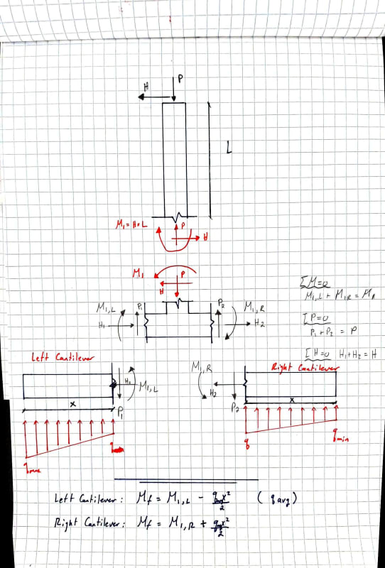
@r13: Yes I agree with you. I have attached a new figure, explaining what I am trying to explain.


M1 is the moment from the external forces, and my understanding is that it is transferred internally to the cantilevered footing below, as per internal stress equilibrium in my figure.
I also understand that this moment causes a non-uniform soil stress distribution below the footing.

That being said, there should be two sources of moment acting on the cantilever: the first from the external moment, and second from the soil pressure.

This is what I am not understanding - why is the internal moment M1 ignored in the design of the cantilever?


Document_19_2_f8je0b.jpg
 
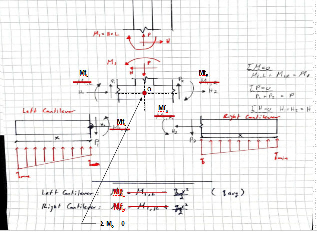
Because it causes the soil pressure moment. You don't need to design for double the moment. If the applied moment wasn't there, the soil moment wouldn't be required.
 
Note M[sub]1[/sub], Mf[sub]L[/sub] and Mf[sub]R[/sub] are all internal reaction at the critical face.

image_ajpjd6.png
 
@Jayrod:

Ahhhh I see it now.

There is a balancing moment from the soil distribution below the footing.
The centroid of the footing pressure is not along the centerline of the column, and that will cause the "restoring" moment for equilibrium.
This moment is equal to M1 from the lateral force on the top of the wall.

That makes sense.

So, my figure above is in correct. It would be correct if it showed a uniform soil pressure below the footing, otherwise I am designing the footing for 2 * M1.


Status
Not open for further replies.

Part and Inventory Search

Sponsor