Eng-Tips is the largest engineering community on the Internet

Intelligent Work Forums for Engineering Professionals

Design of special truss moment frames

Status
Not open for further replies.

compe_ad

Civil/Environmental
Apr 20, 2022
71
0
6
US
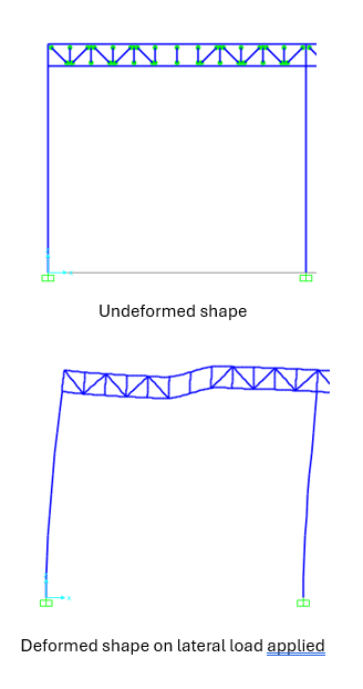
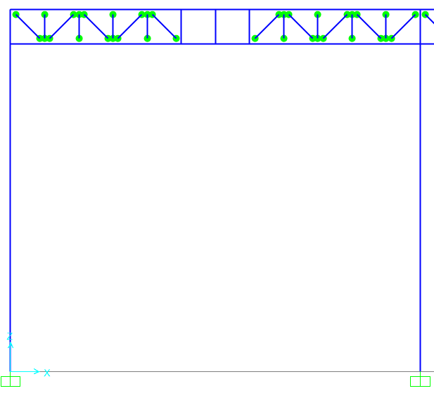
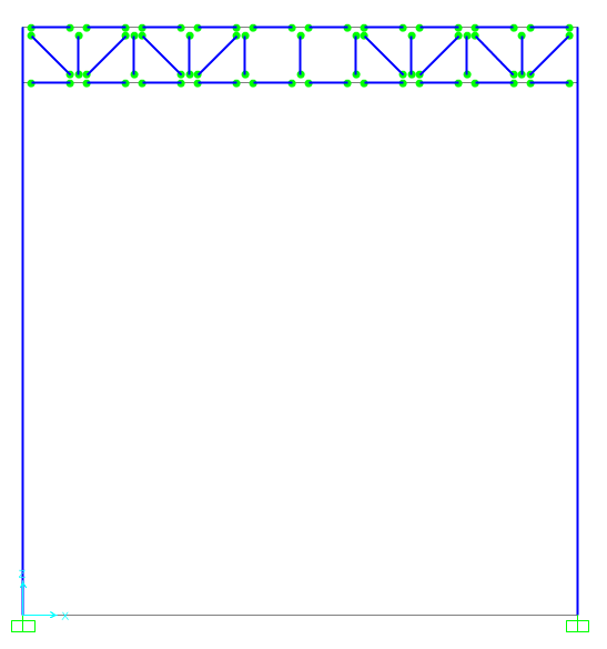
Hi all! I am designing a special truss moment frames in SAP2000. I have pinned the ends of all truss members (see attached) and i think it should be like that. When I ran the model it gives warning message saying structure is unstable or ill-conditioned. Am I doing it correctly?
Please recommend if you know any papers or worked out example related to STMF.
STMF_pqde9f.png
 
Replies continue below

Recommended for you

just a 2d model? or is it 3d? I'm not personally familiar with SAP other than to know it exists.

Why do you not have diagonal webs in the middle of your truss? That is ill conditioned. If you're eliminating diagonals, then the vertical web to chord connection must be fixed for it to act like a vierendeel truss.
 
I fixed it by changing couple of things in my model. It is a 2D model. Yes I am designing it to act like a vierendeel truss. Why do i need to have vertical web to chord connection fixed? Can you please elaborate or provide some references if you have any?
STMF_jj9voy.png
 
because that's how a vierendeel truss works when considering only vertical webs. Now that you've added chord continuity to your model, it doesn't appear necessary, but you'll note the added deflection/flexibility in your truss at that location. Essentially without diagonals, or the webs being fixed to the chords, your top and bottom chords will need to be designed for an unbraced length equal to the length between diagonals. The web to chord connection being pinned in the centre where you only have verticals would allow the web to just fold over if it tried to restrain chord buckling.
 
jayrod12 said:
Why do you not have diagonal webs in the middle of your truss?
SWComposites said:
why would you not put diagonals in the center two bays??? you are creating hinges in the middle of the truss.

OP said he was designing a Special Truss Moment Frame. Those require a special segment in the middle of the truss where deformation occurs for seismic design. I've never personally designed one, but the reasoning is there.

Go Bucks!
 
those missing diagonals "neuter" the whole frame's lateral stability. If you can't have diagonals here, then you need to make these frame elements beams, to carry the upward load form the inner (unbalanced) vertical members.

"Hoffen wir mal, dass alles gut geht !"
General Paulus, Nov 1942, outside Stalingrad after the launch of Operation Uranus.
 
You might need the opening for mechanical stuff, or whatever. With the two diagonals missing, the truss can still be designed.

-----*****-----
So strange to see the singularity approaching while the entire planet is rapidly turning into a hellscape. -John Coates

-Dik
 
I can't remember how SAP deals with this. But in other programs, if you have so many members framing into a single node, and you release all of the member ends, the node itself becomes unrestrained for rotation. Ensure that you have adequately restrained all the out of plane translations and rotations for each node in the 2d model.

For those commenting on the lack of diagonals, please refer to the design guidance for special truss moment frames in AISC SDM or other similar reference. The OP referenced this specific system in the post, and the lack of diagonals in the special panel zone is very much the design intent of this seismic system.

If you want special zone with Vierendeel trusses then I would model the top and bottom chord as continuous (or at least continuous up to actual shear splice locations), and the webbing the special zone should also have fixed ends.

 
I made the changes on my model. I think the webbing on special zones have fixed ends to develop the plastic hinges, correct?
STMF_mzph35.png
 
OP said:
Please recommend if you know any papers or worked out example related to STMF.

Start with section E4 of AISC 341-22 if you haven't reviewed that already: Link. You can use vierendeel action for the special segment if there are no significant gravity loads there. Other wise, you truss the special segment which, of course, limits the spiffy ability to accommodate mechanical runs there.

c01_wvfw4n.jpg
 
Has anyone design STMF before? I have read the AISC code and some research papers. I came to conclusion how I will design the frame.
1> First make a 2D model and find the shear demand on the special segment of STMF. Select a section for the special segment which has expected vertical strength calculated from E4-5 greater than the shear demand.
2> Design of elastic segment-> Consider the portion of the 2D model and add a vertical expected shear as a load to the structure (see figure). Add this expected shear load case to all load combinations. Determine the demands on all other members of trusses and also columns and design for this load.
3> Provide the necessary detailing based on AISC.
Please let me know if there is anything.
STMF_hspqhx.png
 
all those sketches use beam caps to carry the transverse shear over the last bay (without the diagonal).

"Hoffen wir mal, dass alles gut geht !"
General Paulus, Nov 1942, outside Stalingrad after the launch of Operation Uranus.
 
Status
Not open for further replies.
Back
Top