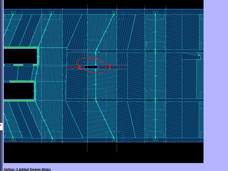
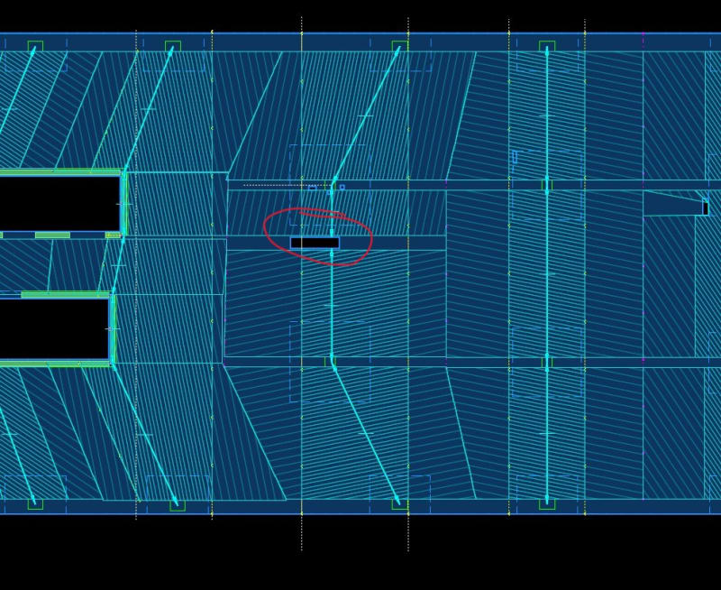
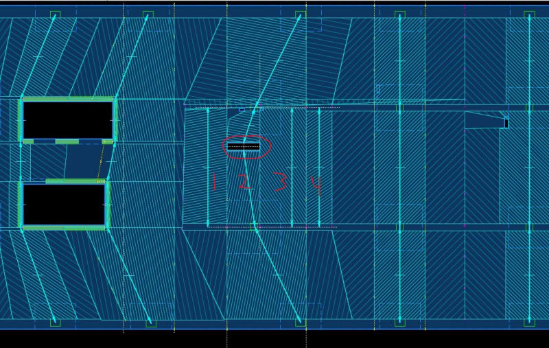
This is for a large opening in the middle of a column strip in a two-way slab. Below I show two different longitudinal design strip layouts. The first just starts and stops the longitudinal design strip on each side of the opening. The second adds design strips on each side.
My questions are:
1.) Are both permissible?
2.) This is a detailing question that is somewhat specific to ACI and RAM Concept - If you are familiar with RAM Concept, would the end of the span be considered cantilever or support? Said differently, do you think it is required for top bars that are in the design strip of the opening to extend all the way to the opening or can they simply extend as far as needed for strength and or typical span detailing requirements?
My thoughts:
The difference between the two designs is that you are most likely going to get more top bars in the 2nd option ("added strip" method) at the narrow strip that algins with the opening. The first method (single strip) seems to average out the demand moment over a wider strip. Using cantilever option at the opening just tells the program to extend the top bars to the edge of the opening.
If this were a new design, I would probably use added strips on each side of the opening and denote the end as cantilever (this seems most conservative). However, I'm really trying to sharpen my pencil to evaluate an existing condition. It seems permissible to use the first option (single design strip). I can't think of any code provisions that this would be violating. Meaning that the column strip width is still being used to determine the amount of reinforcement. Not saying this for sure means it's ok, but basically it comes down to what width you can use to "average out" your demand moment and capacity. The argument to denote the end of the span as a support would be that the latitudinal strip supports the slab. Meaning that the end of the span isn't truly a free cantilever.
Option-1 Single Strip
Option-2 Added Design Strips
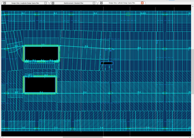
Latitudinal Strip For Reference
My questions are:
1.) Are both permissible?
2.) This is a detailing question that is somewhat specific to ACI and RAM Concept - If you are familiar with RAM Concept, would the end of the span be considered cantilever or support? Said differently, do you think it is required for top bars that are in the design strip of the opening to extend all the way to the opening or can they simply extend as far as needed for strength and or typical span detailing requirements?
My thoughts:
The difference between the two designs is that you are most likely going to get more top bars in the 2nd option ("added strip" method) at the narrow strip that algins with the opening. The first method (single strip) seems to average out the demand moment over a wider strip. Using cantilever option at the opening just tells the program to extend the top bars to the edge of the opening.
If this were a new design, I would probably use added strips on each side of the opening and denote the end as cantilever (this seems most conservative). However, I'm really trying to sharpen my pencil to evaluate an existing condition. It seems permissible to use the first option (single design strip). I can't think of any code provisions that this would be violating. Meaning that the column strip width is still being used to determine the amount of reinforcement. Not saying this for sure means it's ok, but basically it comes down to what width you can use to "average out" your demand moment and capacity. The argument to denote the end of the span as a support would be that the latitudinal strip supports the slab. Meaning that the end of the span isn't truly a free cantilever.
Option-1 Single Strip
Option-2 Added Design Strips
Latitudinal Strip For Reference