Eng-Tips is the largest engineering community on the Internet

Intelligent Work Forums for Engineering Professionals

Design Structurally a Wet well (Lift Station) 1

Status
Not open for further replies.

Rpardo_A36

Structural
Jan 29, 2024
6
0
0
US
Hello all,
I am fairly new to this, so I am designing my first Pump station that contains a Wet Well.
I would like to know what software and process are required to complete a design like this.
My wet well contains a 2' top slab with 2' walls and a 4' bottom slab along with a seal slab.
connected is a discharge chamber that will be cast in place and reinforced.
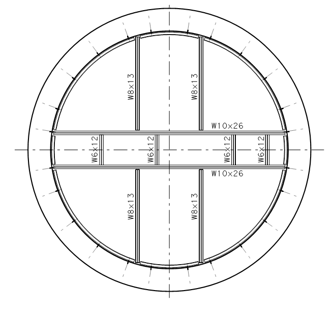
inside the wet well will contain a platform for a trash rack with design size grating, Steel beams of W shape & angle Shape with fasteners.
Beams will be anchored to the wet well.
I am stuck on design the grating, steel beams (along with bracing), and anchorage from steel beams to wet well walls.
Thanks all,
-RP
 
Replies continue below

Recommended for you

What diameter is your lift station? Also, is it a sanitary or stormwater lift station?

In my experience, you can easily do pre-cast designs for 6ft and 8ft diameter wells. You can technically go up to 12ft diameter with pre-cast, but every time I try and do that; I run into issues with the amount of steel in the precast sections. I have found that it is easier to show a cast-in-place design on the plans; and then say 'at contractors option, a signed & sealed ACI 350 compliant pre-cast design may be submitted for engineer's review and approval."

 
JoelTXCive, if it is round, you can just follow the ASTM circular riser reinforcing standard? I forgot what ASTM it was. I dont remember seeing any depth associated with it.
 
Thanks for your response, this will be a precast wet well with a Cassion method for construction.
I have designed the wet well of the walls, top slab, and bottom slab.
This post will be more direct to the steel beam design and Grating design within the wet well.
 
I dont understand why you are confused. Design the beam the the equipment DL, add maybe 40 LL, use the load factors, design the steel beam. Design the anchor bolts into the concrete per the reactions you got. The grating, you dont need to design anything, the supplier should have span rating for certain LL you want.
 

RPardo - What diameter pipe?

The hard part on the steel platforms or debris screen is attaching them to the walls. Your going to be limited by the anchor bolts into the pre-cast section, which might be only ~8 inches thick.

 
Rpardo A36, we get this kind of question a lot. We can and do help, but the best place is your co-workers. Your company likely has a design on the shelf and people there who are financially motivated to help you.
None of this is difficult, but there's some tricks of the trade that can make the design more efficient and robust.
 
thank you for all the responses, so any recommendations on the best software to use to obtain the reactions created from DL & LL? or is this something that is no way of going around and we just need to do hand calculations?
 
You can use software, but the vertical loads on this system are not an analytical complexity unless there's some complicated framing happening. It's pretty much a minute or two of math that derives directly from your load inputs. The inputs and load path are the critical thing and software doesn't do that figuring out for you.

Not trying to be a jerk about it, but do you have the background to be doing this part of the work? The question just feels like the wrong question to be asking.
 
You can use software, but for something this small......

Calculate the tributary width of your beam,....and then wl^2/8 for the moment and wl/2 for the reactions.

 
TLHS, for this type of wet well calculation no I haven't did this part of work, this is a first for me.

JoelTXCive:
thank you for this, yeah that was the way I was going but I was hoping to find an easier route, so basically using basics "statics" finding the reaction of each beam.
below is what I am dealing with. Design the steel beams considering DL, LL, and grating weight (dl).

Capture_nbr9io.png
 
When I posted earlier, I mentioned "tricks of the trade." One of which is the use of steel in a wetwell. There's likely to be corrosive gasses that would eat up steel, pretty quick. Even if it's potable, it will be moist. For something small, aluminum is more resistant to corrosion.
 
Rpardo -

Is that the platform? or the debris screen at the bottom.

Also......what is the well diameter? (I've asked this 3 times)

Regardless of being the platform or debris screen, I would get rid of the W6 beams and the W8x13's. Replace with W8x18 or W8x24's. Two reasons...

1) you are going to have grating that requires minimum ~2" of bearing per side on the beam flanges. A W8x18 has a 5.25" flange to catch the grating. I like the W8x24's because they have 6.5" flange, which provides some margin of error for the contractor.

2) Connections...a W8 beam has a "T" dimension of 6.5" in the web, which will allow you to get a full size bolted connection between the beams. The smallest standard AISC connecting plate (or angle) length is 5.5" so you need to pick a beam with a "T" dimension larger than 5.5". (See the single plate and single angle connection details in Section 10 of the steel manual)

Generally speaking....just due to the geometric requirements for the connections and providing bearing surfaces for the grating, you will have significant excess capacity in the beams. Your weak link is going to be the connections to the concrete walls. You're going to be limited by what you can pass through Hilti anchors.


Status
Not open for further replies.
Back
Top