Eng-Tips is the largest engineering community on the Internet

Intelligent Work Forums for Engineering Professionals

Designing a Balanced Rotating Shredder

Status
Not open for further replies.

Wizard_design

Mechanical
May 14, 2019
4
0
0
US
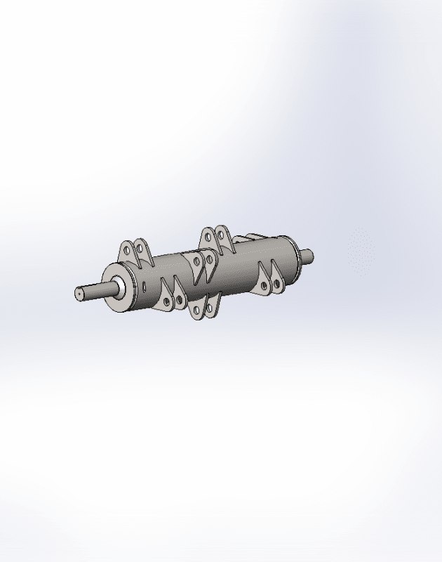
I am trying to design a balanced drum with equally weighted/spaced ears to spin at 1450RPM .

I just started learning about dynamic balancing so my grasp of it isn't completely solid.

I originally designed this machine so the drum had its static center of gravity at 0,0 thinking this would be a enough to produce a balance machine.
After building the machine and running it; it was clear this wasn't correct thinking. So i started doing research and discovered that statically balanced does not mean that it is dynamically balanced.

My first question is it possible to place these ear in a way that (theoretically) no extra balance weights are needed?

Is there something simple I'm overlooking? It seems like with equal radial distance and equal weights there should be a way to place these so it is dynamically balanced.

Because I'm human I was trying to keep the tabs in some kinda of sensible 60 deg arrangement or 72 deg arrangement. is this sabotaging the design?

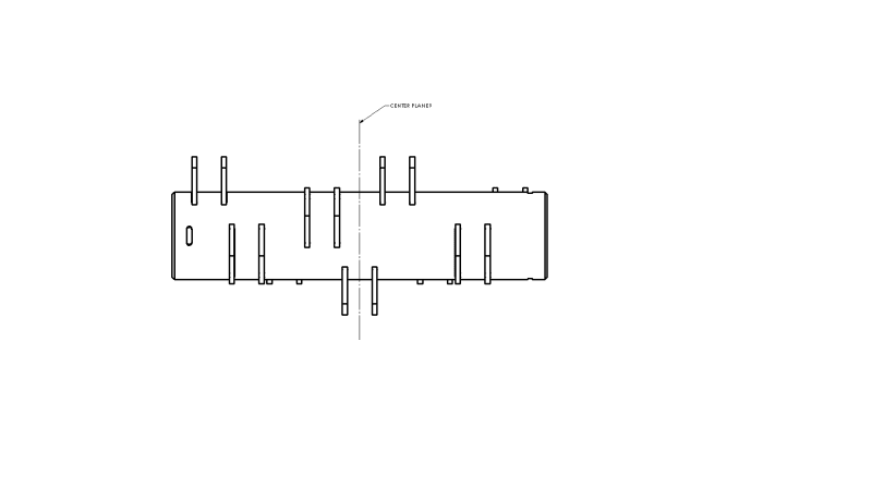
Here is what I have now:

Goal:
To have a dynamically balanced drum with 9 equally spaced/weighted ears

technique:
I am using the 2 plane balance method (graphical and analytical both seems to work for me)

Knowns:
All the added weights are the same, all the distance along the axis of rotation between weights are the same.

Unknowns
angular placement of ears (Im setting 0 degrees to be in line with ear 1) .


(I realize due to manufacturing tolerance some weight will be necessary, we have a VibXpert 2 (from Pruftechnik) hand held vibration analyzer to help final balance)

Or how do we get as close to 0 added weight as possible.

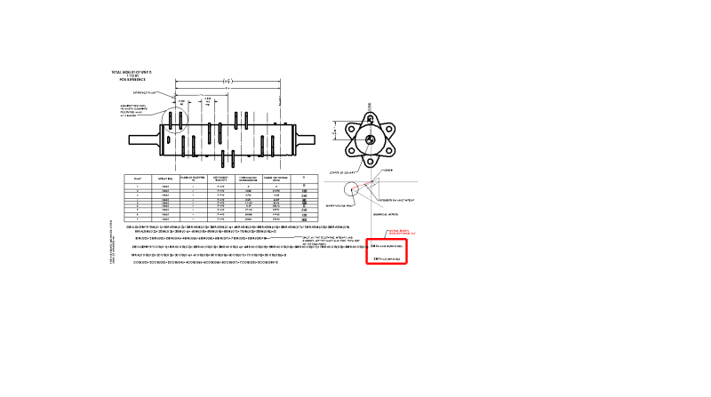
I am trying to solve the moments off the center of ears 1, I attached a PDF that shows my work and my thinking (again I am new to this) looking for guidance and to make sure I'm not chasing my tail on this one.

So far I have 8 unknowns and 2 equations.

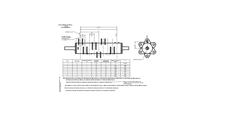
I have attached my work below along with a picture of the rotating piece in question.
Thanks for taking your time to read, any help would be greatly appreciated
understanding_balance_hdavvu.png

understanding_balance-2_io3cp3.png

011153_mrqbl7.png


Replies continue below

Recommended for you

If you want pure theoretical balance, you need radial symmetry AND you need symmetry about the center plane.

You have radial symmetry, but the center plane asymmetry will add a second mode that is out of plane with the plane of rotation.

You could solve this problem by either moving the ears so that there is center-plane symmetry, or by adding counterweights opposite the mounting ears (which would require you to balance the full assembly instead of just this 'rotor').
 
jgKRI~ Thanks for the reply.

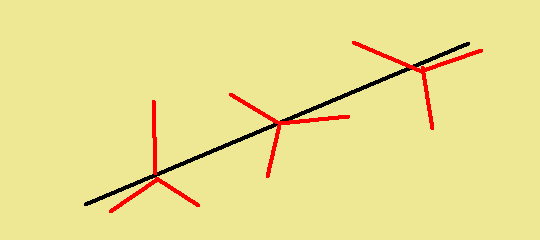
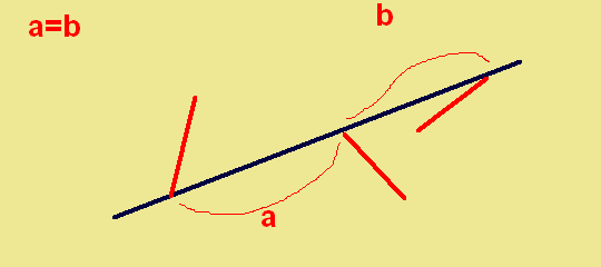
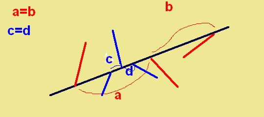
When you say center plane, is this what you mean?

would that mean that having an odd number of eccentric weights make it so you cant get a theoretical balance?

centerplane_re0sey.png
 
Yes-that is what I mean.

I would suspect that if you instrumented the feet or legs of your machine, you have a 2nd order waveform through that plane.

If you use counterweights to balance each load point on the shaft, then no- the odd number of eccentric masses will not present a problem.
 
IF you consider the rotor to be rigid, then the above approach seems reasonable (targeting static balance and targetting mass symmetry about the axial center plane).

Maybe it is implied that you consider the rotor rigid in your question where you indicate an intent to balance in two planes. But I think it’s worth questioning – do you know for sure that this rotor is rigid at the running frequency of interest (first flexible rotor critical significantly above operating speed)? If not, then the approach above still doesn't guarantee that you are not going to excite a flexible mode. A careful modal analysis might help to determine potential modeshapes of concern in the frequency range of interest, which could help in the design.


=====================================
(2B)+(2B)' ?
 
The design shown as not good because of the asymmetry along the rotor length, as mentioned. The rotor structure should be also designed with 1st bending mode natural frequency 15-20% above shaft speed, including the attached hammers. Typically the bare rotor would be trim balanced (probably 2-planes) and then the attached hammers weighed (static or moment weight)individually and installed to minimized unbalance force. I "balanced" a 2000-hp 1800-rpm shredder at a trash burning power plant. Not an easy task.

Walt
 
>To have a dynamically balanced drum with 9 equally spaced/weighted ears
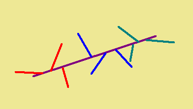
Hmm.. 9 = 3 groups x 3 ears at 60 degrees. this should work, because each group is symmetrical about the shaft axis. If the ears are shifted relative to each other along the shaft - this is not a problem if the shaft is rigid. Also, each group can be rotated relative to the other group around the shaft axis - this is not a problem too.
I think so.. )

shreder_lki3tj.png
 
diakin~
While this technique will give you static balanced rotor (Center of gravity at center) It is not enough to be dynamically balanced.

If something is statically balanced it is not therefore also dynamically balanced.
If something is dynamically balanced it is therefore also statically balanced.

I don't have enough knowledge to fully wrap my head around the reasons, but it has to do with balancing the moments around the bearings.

I have figured out the equations to solve the problem, both analytically and graphically, which has helped me move forward with the design.

I have found that going to 8 blades will give me a designed balanced system. For 9 blades I haven't found a good way to design it so it is possible to build, be functional, and be balanced, without planning on adding counterweights.

My team is deciding whether to switch to 8 blades or to design around 9.

thanks for all the help.
 
Dynamic balancing as you describe is sufficient for a rigid rotor, but not for a flexible one. This thing looks like a thin rotor with a long distance between bearings. At 1450rpm, it’s not obvious to me that it’s rigid unless it’s a lot smaller than I’m imagining.

If you can provide rough dimensions of the rotor and materials (i.e. is it steel), and a rough description of the bearings, we can provide a more educated opinion. I can try a very rough calc (sweeping the unknown bearing stiffness through a range of values).

It looks like some of the needed dimensional information is in your first posted graphic, but the quality of the jpg is too poor to read anything from it.


=====================================
(2B)+(2B)' ?
 
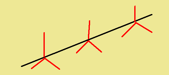
For 9 ears simplest scheme dynamically (and statically) balanced is this (120° between ears in every group)
sss4_hv7cg0.png

pic.1
Each group is symmetrical and therefore balanced.

also every group can be rotated in any angle - symmetry is not broken
sss5_pzqsqb.png

pic.2
and in this case - (imho) rotor is statically and dynamically balanced too. (120° between ears and equal distance between the ears)
sss3_qdpb1e.png

pic.3
and you can add several distributed groups - and rotor will statically and dynamically balanced too.
sss6_kqivwe.png

pic.4
Yes, this is true for rigid rotors.


WBR, Andrew
 
Electric Pete:

The drum is 29.5" long, 6.625" diameter witha thickness of .3125". The ears have run on a diameter of 9.425" . For 8 rotors I have center spacing between ears at 3.266", and for 9 ears I have the center distances at 2.858". It is all mounted to a 1 15/16" dia shaft. The rpm is 1450RPM. Each blade is 8.5 lbs. We are using Timken 4 bolt bearing flange (YCJ 1-15/16).

Thanks!


I did some poking around, and I think my concern was unfounded for your particular case. In other words, I think your rotor is rigid enough that you can consider it a rigid rotor for balancing purposes.

I analysed the system using a transfer matrix method, which took into account mass of the shaft, stiffness of the shaft, mass of the drum, gyroscopic effects of the drum.

I did not take into account stiffness of the drum (because that would be harder). It is a conservative assumption because the system would act even more rigidly if that was modeled.

I did not model the particular tabs (because I don't have that capability). But I think they are a small portion of the total mass so it shouldn't change the conclusion on the modeshape of the rotor. We can treat them similar to typical unbalances and balance weights: they determine which modes might be excited but they don't substantially change the modeshapes or associated frequencies.

I assumed the bearings are rigidly anchored to ground, not to some other mass that might move. (if there is significant movement in a massive bearing pedestal or support, that would invalidate the analysis).

Slide 1 = rotor geometry (drawing)
Slide 2 = rotor geometry (numerical table)
Slide 3 = critical speed map. System was analysed over a variety of bearing stiffnesses and critical speeds were plotted with frequency on vertical axis and bearing stiffness as horizontal axis (treat bearing stiffness as a variable / unknown).
A typical thumbule is that rigid balancing is acceptable below 75% of first flexible-rotor critical frequency. I applied some more conservatism and made it 50%. So we are looking for any flexible rotor criticals occurring below ~ twice operating speed ~ 50hz.

Slide 4, 5, 6 examine bearing stiffness multipliers of 0.1, 0.01, 1.0. My conclusion is there are no flexible rotor criticals below 50hz. (of course there’s always the possibility I have made an error, but that’s the way things go on forums). Looking for the closest modeshape of concern in slide 4, if anything you'd want to avoid a configuration that creates an imbalance near the axial center of the rotor (you probably don't need any fancy analysis to figure out that the first flexible rotor critical will have a modeshape with anti-node in the center).

Edit - I also did not model whatever structure connects the drum to the shaft, because A - I don't know the details; B - it wouldn't be easy.

=====================================
(2B)+(2B)' ?
 
 https://files.engineering.com/getfile.aspx?folder=a6b34c40-4483-4a9c-ad71-09e362fce8dc&file=SHREDDER.pdf
Status
Not open for further replies.
Back
Top