Eng-Tips is the largest engineering community on the Internet

Intelligent Work Forums for Engineering Professionals

  • Congratulations waross on being selected by the Tek-Tips community for having the most helpful posts in the forums last week. Way to Go!

Designing Moment Frame for Residential 1

Status
Not open for further replies.

TORCHMAN

Structural
Sep 8, 2023
68
0
6
CA
Good Evening,

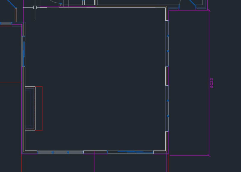
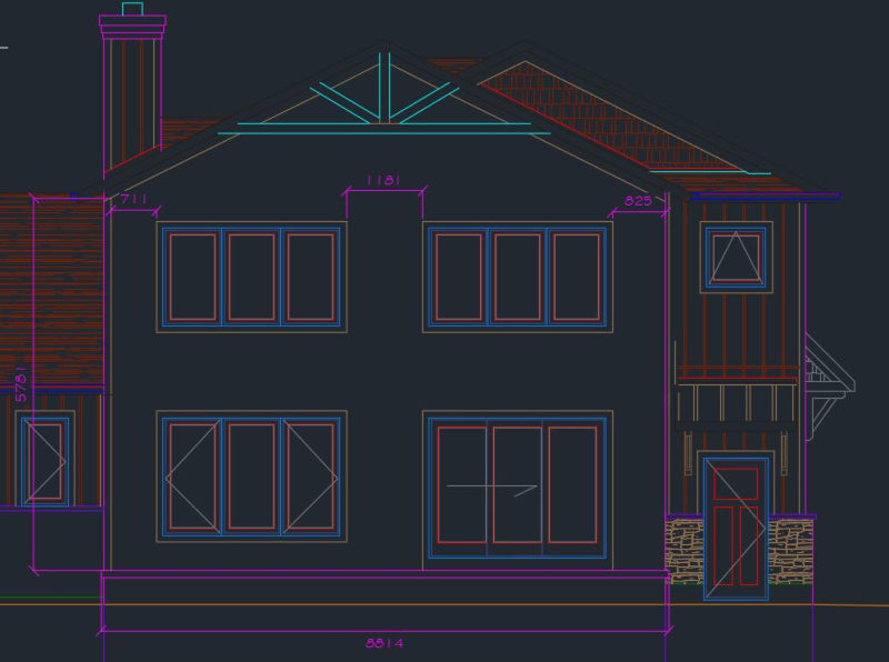
I am designing a moment frame for a house and want to run some ideas by you and see how others engineers would approach this. It is an existing house and a proposed addition is being designed. This addition is a great room with a scissor truss. The exterior walls are about 5.5m tall without a mid-floor in this section of the addition. As it concerns the lateral stability, I am not concerned with the one side (north side on the plan) as it meets the existing structure creating stability as it ties to an existing roof and has a mid floor. On the south side, however, it has the tall walls and large openings. With the wood code in my area limiting shear walls to having a height no taller than 3.5 width of the segment of shear wall, none of my walls can be used as shear walls. Plan and Elevation Below
Moment_Frame_House_Plan_g0eofb.jpg
Moment_Frame_House_Elevation_epn850.jpg


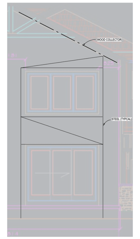
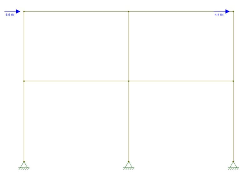
I find the use of moment frame to be the correct approach in this situation. Let me know if you agree. If so, I have modelled as per below. In such case, I am still getting some large deflections but I am not using the wood framing in the model which will help to stiffen this frame. How do you propose I use it in my calculations? Should I use a better software and model it as a plate? Or should I not use it at all?

Columns are HSS 127x127x9.5
Beams are W200x21

Moment_Frame_fz88ix.jpg
 
Replies continue below

Recommended for you

Two things to think about when putting a moment frame in a residential scenario:
1. What style of moment connection is preferable for design?
2. Is there enough space for the moment frame footing?

With respect to #1, your options become limited with HSS column and W beam. Keep this in mind if you are designing in a seismic area where it may be anything other than Rd=1.5 Ro=1.3.

The analysis usually requires some iterative work. The load distribution is based on stiffness, so you need to come up with an initial distribution between the moment frame and the shear walls (existing structure) and review that number based on how much everything is deflecting. Keep in mind that the load applied should be based on the lowest Rd Ro value.

I think your modelling approach is probably correct. Not sure how or why you would model it with a plate.

If your drift is governing that may be due to the Ix of HSS5x5x3/8 being 9.48x10e3 mm3. Looks like you are trying to fit in a 2x6 wall or something. Have you considered using a W360x33 (Ix = 82.7x10e3 mm3)...Class 1 column, stronger than the beam, still fits within a 127mm wide cavity, decent flange, capable of standard pre-approved moment connections, etc. etc.
 
Thanks @skeletron, all great points.

I believe the skinny W beam in the wall makes more sense. You are right, I am trying to fit it into a 2x6 wall. And wind rules in this case.

For the plate idea, I mean that there is framing that will infill between the beams in the moment frame, despite there being large openings inside, I believe it will stiffen the frame.

With regards to the moment frame footing, I plan on having just 2 threaded rods to the foundation wall. There is not much of a vertical load on it, with the max. uplift being about 12 kN.
 
@doublestud - Not in this area. Just a tall wall, no joists at midpoint

@XR250 - not sure if I get the wood collector idea. And the diagonal members, what do you picture them being?

@bones206 - They have tall Strong-Walls this tall, but when flipling through the literature, I found that the shear force due to wind is higher Strongwall allows to meet L/500 deflection. Even if I fit 2 strong walls, the max shear force I can have to meet deflection is 5.6kN. The shear force I have is 9.9kN. This is unfactored load per LRFD. Below is the snip of their max. shear to meet L/500

StrongWall_ivtzzw.jpg
 
Can you fit a double sided shear wall in the middle wall pier?

edit: in my haste, I totally forgot about those pesky aspect ratio requirements.
 
Looks like the table you checked in for the wood version of the Simpson strongwalls. Maybe the steel version would get you over the hump?
 
I agree with those suggesting a Simpson Strong Wall. Run it up to the bottom chord of the truss.

That being said, if the only solution is a moment frame, I would think increasing the thickness of the wall is the least of the issues. The owner won't be giving up much square footage to achieve the view s/he desires. I suggest running the frame to the bottom of the truss to provide lateral stability and putting a "kink" in the beam to follow the roof line. That should provide adequate bracing particularly since drift will probably control the size of the members.

My two cents.
 
Torchman, I am not familiar with metric system beams but it appears that beam is very small. You need very deep beams and columns that will fit your wall (narrow and deep). I believe you can make it work. You may request lowering the top windows so you can fit deeper beam. Perhaps start with W410X46 or W460X52. These beams are narrow enough to fit inside a wall. I would probably use the same member for the columns as well.

If those don't work, you can always make this one wall thicker and use wider members.
 
TORCHMAN said:
@XR250 - not sure if I get the wood collector idea. And the diagonal members, what do you picture them being?

Wood collector - to transfer the shear into the frame.

Diagonals - Steel tubes usually work nicely in these situations. You can always make the walls 2x8 if needed for more space and greater out-of-plane capacity
 
@SE2607 and @bones206 - The steel one works! Beauty!

@DoubleStud - I will try to model with the recommended sizes!

@XR250 - Sorry, I am having a hard time picturing this. Is there a picture you could share or a similar system.
 
Status
Not open for further replies.
Back
Top