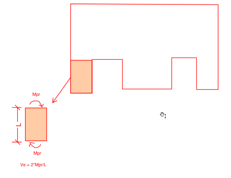
1) Mpr for columns at each end will be same given that the same reinforcement is present at the top and bottom of column, isn't it?
2) How Pu is related to the Mpr values?
3) We will not have beams in this case. So check for Mpr of beams is excluded right?
4) Ve shall not be less that factored shear calculated by analysis. What does this actually means?
Can some one explain this in simple terms? If there is any reference calculations please share. Thanks.