oharag11
Mechanical
- Jun 18, 2015
- 42
So, I just started using CREO and used the detail view callout tool. I was surprised that the circle drawn was solid. I asked a colleague, but we couldn't figure out how to change this. So, I went to SolidWorks to give it a go. No, SW is solid as well. You can change the line style - though it is buried deep in settings. What I didn't like is it also changed the callout line as well. Weird.
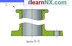
So, I have made detail drawings before - many times, and I never even thought of this issue. I have used CREO, SW and NX. So, from my memory from NX - the Detail View circle was phantom (see attached).
I don't know the ANSI drawing standard, and I tried searching for the allowable line styles for the Detail View circle. Can anyone comment? I'm posting because I want to learn.
So, you'll ask why not keep it solid. So here are my thoughts:
- I would prefer to be able to change this from solid to maybe phantom to designate the circle to be different from physical part lines. Even if I could change the line style of the circle - maybe make it bold that would be something.
- Our machinist just today asked whether the circle was a counterbore or a pocket. Yes, there is a callout flag but I still think the circle needs to be not solid.
Thanks

