Continue to Site

Eng-Tips is the largest engineering community on the Internet

Intelligent Work Forums for Engineering Professionals

  • Congratulations MintJulep on being selected by the Eng-Tips community for having the most helpful posts in the forums last week. Way to Go!

Determining Allowable Loads in Fiberglass Reinforced Piping

Status
Not open for further replies.

vwmeche94

Mechanical
Jun 23, 2011
3
Good morning,

I am in the process of completing a data book for an H2O filter skid for customer and they've asked for allowable load calculations (Forces - axial, circumferential, longitudinal; Moments - axial, circumferential, torsional).

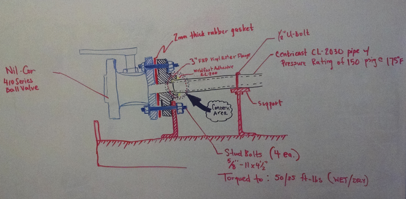
I'm not sure how to get to this as is completely different it seems for the MOC which is Centricast CL-2030 piping with CL-200 adhesive joined to CL Vinyl Ester flanges in size from 1, 1-1/2, 2 and 3 inches.

The picture uploaded is an example of how the FRP piping system along one run is attached to the skid with bolted and padded supports.
IMG_20160204_152351130_iwtkg3.png


See Manufacturer document and lend any advice as appropriate, many thanks.
 
Replies continue below

Recommended for you

It looks like the Tie Point is an Expansion Joint. Is that correct?
 
Vendors usually come up with requirements such as "Zero forces and moments" and then force the Contractor to provide an estimate.
 
Vendors usually come up with requirements such as "Zero forces and moments"

To the amusement of stress analysts all over the world.
 
Ihad to zoom into your sketch to see what you were getting at.

If the flange is as you show then this looks woefully short of a proper flange and a bid stress concentration at the end odds the flange.

If your that worried about the moment on the flange end just make that support all encompassing and able to provide support to the top of the flange.

I think there h are better flanges than that though....

You can model grp piping in ceasar.

Remember - More details = better answers
Also: If you get a response it's polite to respond to it.
 
First, thank you all for responding, I greatly appreciate it and apologize for my delayed response; being laid-off was a bit of a shock and many adjustments had to be made as we are not in a position to relocate with kids in school right now, especially one with autism.

Second, to answer your questions or address comments; No, this is not an expansion joint. I may have shown too much detail in the end connections with the ball flange, gasket and bolting. I only wanted to show what static loads already in place before any field technicians lay hands on any of the bolted assemblies.

As for the remaining three comments, duly noted. Unfortunately, my former employer (and alas, now I), do not have access to Caesar pipe stress software for analysis, but thank you for the great advice.

Fortunately, the Chief applications engineer from NOV contacted me by cell phone on Friday; he provided some great information concerning the mechanicals of the piping and flanges as well as insight on the vinyl ester adhesive that was used and a better (stronger) epoxy substitute. I am reviewing these documents now to learn if what I need is already determined or what additional calculations I may need to perform by hand making some J, M (moments) and Force assumptions based on my personal experience in the field.

Even though no compensation involved, I'm still going to send my findings and answers back to my former employer; my interest is high as this is material I'd only worked with for the last project completed and my understanding is that many customers in O&G and water processing are leaning towards GRP, FRP, GRE, FRE, etc. for their applications involving water, sours, caustics, acids, etc. due to high resistance of the piping material up to certain temperatures.

Respectfully,
vwmeche94
 
Vwmeche94:
I’m not a pipe stress analyst on a daily basis, but here’s some food for thought, based on what I see in your sketch....
1.) I would want more details on the various mechanical properties of the glues, bonding agents, available and being used. I would also talk with the FRP flange manuf’er. about the size and shape of the bonding area/bore into the flg., btwn. the flg. and the pipe. I would always want some more flg. lip(?) length engagement onto/over the pipe, thus more sq.in.’s of bond area. I would like that joint strength to be greater than the strength of the pipe itself. Pay some attention to any stress raisers and the reentrant corners.
2.) I just glanced at the pipe manuf’ers. info. sheets. There seems to be a fair amount of design info. and mech. properties info. there for me to get started on some analysis if I knew what loads you were talking about, and how the pipe was supported in other areas. I might still want to talk with some engineering people at the pipe manuf’ers.
3.) Based on what you circled in black ‘area of concern,’ and the way you have supported the valve and the FRP flg. at that location, I would be concerned about any loading someone else might apply, beyond your control, to the left of the valve. I don’t like the way someone else could crank, in most any direction, and any load, in the plane of the left valve flg.(perpendicular to the axis of the pipe). I don’t like the way the very stiff valve could flex the pipe, on/about your existing simple support to one flg. bolt. I would like that support to be much stiffer and to include at least 3 bolts ( the bolts at 3, 6 and 9 o’clock), preferably all four bolts on the flg. If you could also support the left flg. on the valve, with a similar support, then the valve and any flexing of your pipe would be well supported, and any loads someone else induced would primarily involve their continuing pipe run, not your pipe.
 
I do not recommend that the lower stud be bolted to the lower bracket as you could get a prying action on the end. In my opinion, it would be better to have that end be supported but free to slide. Item No1 of DHENGR is strongly advised as you will need to figure the shear action on that joint.


vwmech,

sorry to hear of your current position - happened to me a few months ago and I hope you get something soon.

Appreciate you're trying to do this properly / analytically, but I think maybe what this needs is just another angle bracket on the inside of the outer valve flange. This would stiffen this end connection up a lot and restrict moment and axial forces. Maybe as dhengr says you need to have a semi circle support with more bolts. Unless that flange gets a lot longer neck which then gradually transitions down to the end, it doesn't matter what glue you use, the stresses on the pipe will be very high.

Remember - More details = better answers
Also: If you get a response it's polite to respond to it.
 
Status
Not open for further replies.

Part and Inventory Search

Sponsor