I asked this same thing on the engineering StackExchange community several days ago.
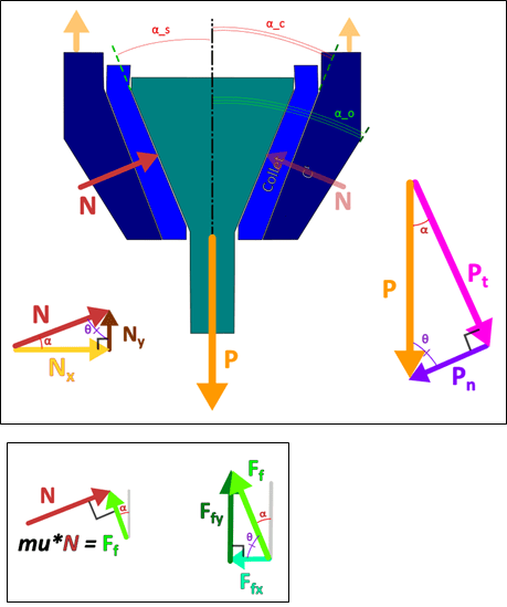
(In the illustration above, the "Collet" piece in the middle is a bushing)
I'm designing an axial linkage of sorts, and I'm having trouble finding resources, theorems, or guidelines for determining the bearing stress between two (truncated) conical surfaces. I'll be intentionally vague on details (materials, application, environment).
I've followed some guidance for modifying thick-walled pressure vessel calculations to determine hoop stress, etc (after reading a thread on this forum). But those formulae assume the (fluid) pressure on the walls is equally distributed. And I can't prove that that's a reasonable assumption in the case of physical, axial loading between the two surfaces. I've worked out friction effects on the share of the loading; i.e. "zero" coefficient of friction between the cones produces much higher normal forces, whereas when friction increases, more and more of the share of the reaction load along the axis is the axial component of the friction force.
I've looked at designs of Morse tapers, but all the info there is surface-level about how to size one, and not the design formulae regarding contact stress between the cones along the length of the axis. I've looked at "wedge anchors" (see Reference 1 at the end), but those are designed as two prism (triangular) wedges sandwiching a flat member, and those calculations don't lead me closer to determining how the bearing stress on the cones behaves-- or they were beyond my capability to follow and ultimately modify for conical interface at the time.
Following "contact" FEA studies (previously referred to as "no-penetration" studies) in Solidworks, most of the surface stress (at and near the interface) is concentrated near the minor diameter (the smaller end) of the truncated cone. And I want to model that by some formula so I can try to manipulate it into more uniform distribution. Part of the issue could surely be deformation of the cones under loading which leads to the minor end being favored. But it could also just be the case that that's where stress tends to concentrate in conical bearing interfaces-- but I can't find anything that outlines this...
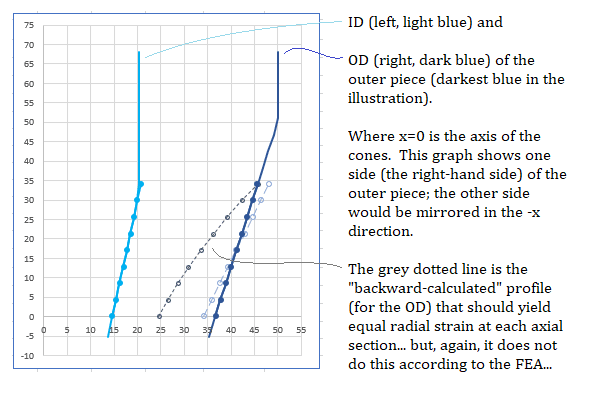
I've tried to manipulate this biased loading result (which, according to the FEA, is towards the minor diameter) by calculating backwards from hoop stress and axial stress to make a profile of the concave cone at 9 different points along the conical interface-- the set of IDs and ODs at each axial cross-section that yields equal (radial) strain at each section, so that the included angle and overal profile of the cone stays more equalized (see below). But the FEA still shows stress bias toward the minor diameter with this manipulated design. And I'm having trouble with this stress concentration (near the minor diameter) giving me Safety Factors that are too low, while staying within dimensional constraints for the design-- I can't make the pieces too wide. However, I am currently assuming that the contact pressure is equally distributed in the thick-walled pressure vessel calculations that I've co-opted... Short of building iterations and making my Excel workbook more of a project than it already is, I'm a little lost about what to look for-- I don't know how to search for what I'm looking for.
Also, at this point I'm just assuming the cones are perfectly congruent. I understand that this is "never" the case. But I'm working with the ideal design, and I'll figure out tolerances after.
Reference 1: Paper titled: "Method of Designing a Friction-Based Wedge Anchorage System for High-Strength CFRP Plates" by Wanxu Zhu, Wei Wei, Fengrong Liu, and Rong Zeng
(In the illustration above, the "Collet" piece in the middle is a bushing)
I'm designing an axial linkage of sorts, and I'm having trouble finding resources, theorems, or guidelines for determining the bearing stress between two (truncated) conical surfaces. I'll be intentionally vague on details (materials, application, environment).
I've followed some guidance for modifying thick-walled pressure vessel calculations to determine hoop stress, etc (after reading a thread on this forum). But those formulae assume the (fluid) pressure on the walls is equally distributed. And I can't prove that that's a reasonable assumption in the case of physical, axial loading between the two surfaces. I've worked out friction effects on the share of the loading; i.e. "zero" coefficient of friction between the cones produces much higher normal forces, whereas when friction increases, more and more of the share of the reaction load along the axis is the axial component of the friction force.
I've looked at designs of Morse tapers, but all the info there is surface-level about how to size one, and not the design formulae regarding contact stress between the cones along the length of the axis. I've looked at "wedge anchors" (see Reference 1 at the end), but those are designed as two prism (triangular) wedges sandwiching a flat member, and those calculations don't lead me closer to determining how the bearing stress on the cones behaves-- or they were beyond my capability to follow and ultimately modify for conical interface at the time.
Following "contact" FEA studies (previously referred to as "no-penetration" studies) in Solidworks, most of the surface stress (at and near the interface) is concentrated near the minor diameter (the smaller end) of the truncated cone. And I want to model that by some formula so I can try to manipulate it into more uniform distribution. Part of the issue could surely be deformation of the cones under loading which leads to the minor end being favored. But it could also just be the case that that's where stress tends to concentrate in conical bearing interfaces-- but I can't find anything that outlines this...
I've tried to manipulate this biased loading result (which, according to the FEA, is towards the minor diameter) by calculating backwards from hoop stress and axial stress to make a profile of the concave cone at 9 different points along the conical interface-- the set of IDs and ODs at each axial cross-section that yields equal (radial) strain at each section, so that the included angle and overal profile of the cone stays more equalized (see below). But the FEA still shows stress bias toward the minor diameter with this manipulated design. And I'm having trouble with this stress concentration (near the minor diameter) giving me Safety Factors that are too low, while staying within dimensional constraints for the design-- I can't make the pieces too wide. However, I am currently assuming that the contact pressure is equally distributed in the thick-walled pressure vessel calculations that I've co-opted... Short of building iterations and making my Excel workbook more of a project than it already is, I'm a little lost about what to look for-- I don't know how to search for what I'm looking for.
Also, at this point I'm just assuming the cones are perfectly congruent. I understand that this is "never" the case. But I'm working with the ideal design, and I'll figure out tolerances after.
Reference 1: Paper titled: "Method of Designing a Friction-Based Wedge Anchorage System for High-Strength CFRP Plates" by Wanxu Zhu, Wei Wei, Fengrong Liu, and Rong Zeng
![[smile]](/data/assets/smilies/smile.gif "[smile] [smile]")