Continue to Site

Eng-Tips is the largest engineering community on the Internet

Intelligent Work Forums for Engineering Professionals

  • Congratulations MintJulep on being selected by the Eng-Tips community for having the most helpful posts in the forums last week. Way to Go!

Determining Moment from different strains of column interaction

StrEng007

Structural
Aug 22, 2014
520
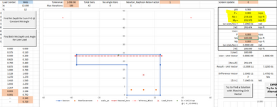
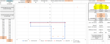
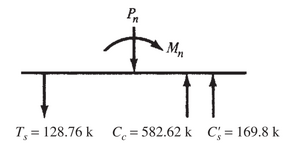
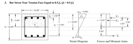
Take a look at the example calculation below. In this step, the column moment is being determined based on a condition where the strain in the concrete is 0.003 and the strain in the tension reinforcing is 0.5Fy/Es or 0.001034.

Based on that information, using similar triangles, forces are determined from contribution from concrete, tension reinforcing, compression reinforcing.

My question is, when summing these forces to determine a moment, why are the forces being taken about the center of the geometric cross section "h/2" and not the dimension "c" which represents the neutral axis?

Screenshot 2025-01-22 162125.png

Screenshot 2025-01-22 162149.png
 
Replies continue below

Recommended for you

So long as you are consistent and get all of the algebra right, I don't believe that it matters what location you choose to take moments about. It's just a matter of computational convenience. This looks like an example contrived to put the compression block at the centerline of the column for just such convenience.
 
With no net axial load on the cross-section it does not matter where moments are summed about since sum H internal=0.

When an axial load is present I find it convenient to sum moments about the geometric center as that is typically how the column will be modeled in an analysis software package so would allow for direct comparison between capacity and applied load.
 
Last edited:
As an example for an "L"

With No Axial Load - moment about the web center:
1737584231716.png

With No Axial Load - moment about the geometric center:
1737584282534.png

The resulting Mx and My values are the same


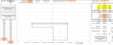
Now with 100 kip axial load -web center:
1737584346552.png

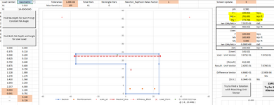
Geometric Center:
1737584376584.png


Here the moments differ by the moment generated from the eccentricity of the Axial load relative to the location used to sum moments.
delta My = -68.182 ft-kips = 100 k * ex -> ex = -0.6818 ft = -8.1818 in
delta x = 3.818-12 = -8.182 = ex

delta Mx = 20.454 ft-kips = 100 k * ey -> ey = 0.20454 ft = 2.4545 in
delta y = 14.454545 - 12 = 2.4545 in = ey
 
Last edited:
I think it does matter.

The calculation is being done to compare the moment capacity of the column with the maximum applied bending moment, so they both need to be taken about the same axis.

Bending moments in a frame analysis are about the centroid of the uncracked sections, so that is what should be used in the capacity analysis.
 
By default, I would use the centroid of the column as the basis for my force calculations. I'm not sure it matters all that much if there isn't any axial load in the column. If there is axial load in the column then you should probably use the centroid.... Since this corresponds to where the axial force produces zero moment.
 
Agree about matching axis used to calculate applied moment. My old textbook used plastic centroid which is location of resultant under pure compression squash load. That gives zero moment for pure compression. Otherwise pure compression case has non zero moment. Only matters for non symmetrical sections. Concrete shape or bar layout.
 
It should be about the plastic centroid, calculated under pure axial. As Smoulder said.

The calculation can be about any position, but it should be transferred to the plastic centroid for the final result.
 
It should be about the plastic centroid, calculated under pure axial. As Smoulder said.

The calculation can be about any position, but it should be transferred to the plastic centroid for the final result.
Why?

Perhaps I should expand on that: Why should it be transferred to the plastic centroid, rather than the centroid of the uncracked concrete section?
 
Last edited:
I ran these calculations about the outside edge of the compression zone. As others have said, as long as you include all the forces it doesn't matter. The example problem I posted takes the moments about the centroid of the cross-section because it eliminates moment contribution from the axial load Pn.

Here is a visual example: Taking all the moments relative to the compression edge and solving your equation for Mn.

Screenshot 2025-01-22 223240.png
 
Shifting gears a little bit. I'm attempting to calculate a load interaction diagram for a CMU jamb (2 cells with a single #5 at each center). This is to determine the capacity for axial loads from a header and the out of plane bending from the wind tributary at the opening. I realize this is not a traditional column, but I've ask the question as to how to handle these scenarios, and I've been told (on this forum) to check it with an interaction diagram.

Overall axial capacity does not take into account axial strength contribution from the vertical bars since they are not tied.

I'm running into an issue when I'm calculating the balanced condition of the diagram (where tensile steel strain is at 0.00207 and the CMU strain is at 0.0025). Here are my numbers, where am I going wrong?

Setting es = 0.00207 (tension steel), em = 0.0025 (masonry)

•Calculating depth of the compression zone for the strain diagram,
c = d/(es/em +1), 3.8125in / (0.00207/0.0025 + 1 ) = 2.086 in

•Stress block depth,
a = 0.8c = 0.8 x 2.086 in = 1.67 in

•Axial forces on section
Compression from masonry = 0.80 f'm ab = 0.80 x 1,500 psi x 1.67 in x 16 in = -32.0k
Tension in reinforcing = Asfy = (2)0.31in² x 60ksi = 37.2k

ΣPn = 37.2k - 32.0k = 5.2k (THIS VALUE IS IN THE OPPSITE DIRECTION; IMPLYING THE SUM OF FORCES IS IN TENSION?).

I'm struggling to understand what this means, and what is going wrong here. I've run a bunch of CMU column interaction diagrams by hand and not had this issue when I'm looking at a conventional 16"x16" column with (4) bars. Typically my sum of forces for Pn gives a negative number (per my sign convention) indicating that Pn is an available compression load.
 
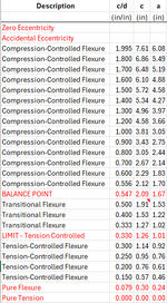
At the balance point, c/d = 0.547 for CMU, and c = 2.09, which you have. Looks like you're using 8-inch block, since d = 3.8125 in for centered bars.

Effective compressive width (b) is the minimum of bar spacing in inches, 6 * the nominal masonry size in inches, and 72 inches. So b would be 8 in, but, on a per-foot basis, the compression block ultimately gets multiplied by 12 in / b, so "Compression from masonry" = 0.8 * f'm * a * 12 in = 24k per foot of jamb, which is the same as 32k for the whole jamb, as you have computed.

As per block is 0.31 in2, yes, but, on a per-foot basis, As is 0.47 in2. So "Tension in reinforcing" = 27.9k per foot of jamb, which is the same as 372.k for the whole jamb, as you have computed.

I also get that the sum of forces is in tension, which means that the balance point lies below the M axis. This means that the jamb falls in the compression-controlled flexure region of the P-M diagram (ignore my blue x below).

1737630574288.png1737630614220.png

Also, isn't the minimum f'm 1,750 psi? From 2022 TMS. My spreadsheet (that I built) has a floor of 1,750 psi. I had to override it for 1,500 psi. I must have had a reason for programming it that way, but I cannot recall the salient code provision that limits f'm.
 
Also, just to throw this out there, given the spread of responses in this thread, moment equilibrium is not dependent upon the point about which moments are summed. As long as the axial compression is properly accounted for in the FBD, then it does not matter where moments are taken. @Celt83 explained it beautifully.

Many textbooks teach simplifications/shortcuts like taking M about the centroid of the compression block such that only the steel forces are needed, which is usually fine but can be problematic when the steel isn't yielded or when the CMU is hollow whereby multiple compression blocks must be summed. I always sum about the section's centroid, even if it is computationally less convenient.

Masonry Designer's Guide (and one other book by the same author) has handy equilibrium tables from which spreadsheets can be readily developed.
 
ANE91,
I appreciate your efforts to explain this. Looking at your table, I yield similar results regarding my c and a values. I did not iterate as many points as you have though and chose to look at benchmark locations as you would do for a simplified approach (i.e., zero strain in tension reinforcing, balanced point, pure moment no axial).

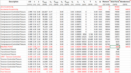
I modified my interaction diagram to include all the iterations of "c" and was able to arrive at a table that reflects your own.

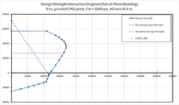
Question: The initial calculation of Pn (all axial, no moment) includes a check on the slenderness of the column element and reduces the capacity by [1-(h/140r)²] or (70r/h)² depending on the slenderness. However, once moment is introduced I've noticed that the column axial capacity allows a fictitious development of axial load (see the 2nd image below) in comparison to the axial cap. The reason has to do with the overall sum of forces on the cross-section not being limited by the slenderness reduction. Is there a way to account for this?

Using the same values as I showed above, and considering a single 16"x8" (nominal) jamb with a height of 10 ft.

Shape of interaction diagram when H/r is less than 100.
Screenshot 2025-01-23 124149.png

Same shape but with a height of 20ft.
Interaction diagram goes wonky when H/r approaches and exceeds 100:
Screenshot 2025-01-23 124236.png
 
At a glance:

Refer to the pink/purple line on my P-M diagram. That’s the slenderness limit. Develop it independently of the first-order strength. After all, the slenderness limit is to account for buckling instability.
 
ANE91,
I'm trying to run a sample calculations and unfortunately the only way I can check my own numbers is to compare them against Enercalc. It seems like the more I use Enercalc's masonry slender wall module, the more I have difficulty following how it does things.

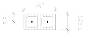
What I'm looking to check is the load interaction for a CMU jamb with the following
Screenshot 2025-01-23 152959.png

•b=16" wide
•h= 8" CMU (7.625 in actual)
•reinforcing is (1)#5 centered in each cell
•Jamb is 10ft tall
•Fy=60 ksi, f'm=2,000 psi

The applied Axial Load is Pu=10k
The applied Out of plane moment is Mu=5 k-ft (simple span wind loading)

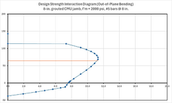
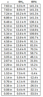
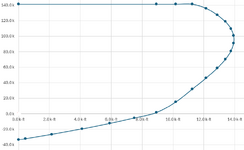
I get the following values from my iteration of c, and the corresponding load interaction diagram.
Note that my Pu, Mu falls within the curve.
Screenshot 2025-01-23 151152.png
Screenshot 2025-01-23 151226.png

Base on your own values, do you arrive at something similar?

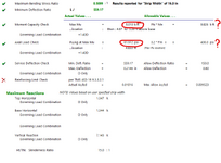
Now, I've tried to compare this to Enercalc by setting up a 16" strip width and inputting all the information above. Enercalc doesn't produce a PM diagram, but it provides the following.

•Notice the input for Mu is at 5 k-ft
•The axial load is 81.912psi x (16 x 7.625) = 10k

The "allowable" moment value for this scenario shows 9.826 k-ft. This seems to correspond with my interaction diagram, if you were to draw a horizontal line at Pu=10k, it would intersect the cure at approximately Mu=9.9 k-ft. I'm assuming this is part of the axial/moment interaction calculation Enercalc does in the background.

However, it doesn't provide an axial load utilization check. Rather, it shows the stress in the masonry based on Pu/Ag, then compares that against 0.2f'm? I'm not sure why it does that.

I can only seem to reproduce values close to this when the members are short. I believe Enercalc is also performing P-d calculations (hence the module being called "Masonry Slender Wall" which is not accounted for in my spreadsheet.
Screenshot 2025-01-23 151935.png
Do you get similar results.
Another question is, rather than program my own spreadsheet (which is essentially already done), are there any spreadsheet resources provided by the masonry associations that does all these calculations?
 
I’ll check it tomorrow.

I don’t have Enercalc, so I don’t know if it uses the Moment Magnifier Method (conservative) or the Slender Wall Method for P-Delta calcs. My spreadsheet defaults to Moment Magnifier. I also cannot explain the 0.2*f’m check.

Elemasonry is a software package from the newly combined masonry institute. Looks slick. I built my spreadsheet using the Masonry Designer’s Guide & Strength Design of Masonry books. I’m unaware of other resources.
 

Part and Inventory Search

Sponsor