Continue to Site

Eng-Tips is the largest engineering community on the Internet

Intelligent Work Forums for Engineering Professionals

  • Congratulations KootK on being selected by the Eng-Tips community for having the most helpful posts in the forums last week. Way to Go!

Development Length of Bar in Cantilever Beam (opposite support) 3

Status
Not open for further replies.

RFreund

Structural
Aug 14, 2010
1,880
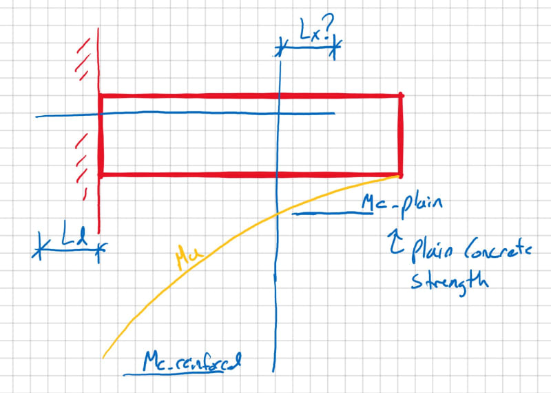
What is the distance that reinforcement must extend beyond the "cut-off" point in a cantilever beam? Where the cutoff point is the strength of plain concrete. Is it Ld?

Development_Length_in_Cantilever_iwgad5.jpg


More context - this is to see if we could enlarge the size of a footing. Basically a footing needs to get larger but the reinforcement is already on site.
 
Replies continue below

Recommended for you

I'd never rely on plain concrete strength for that application. There's not much redistribution with cantilevers and concrete tends to be a brittle material. If looking for a 'cut-off' point then dv beyond the point it is needed.

Rather than think climate change and the corona virus as science, think of it as the wrath of God. Feel any better?

-Dik
 
That's a very fair assessment (and I concur). There may be a provision to have some minimum number of bars for integrity. I'm still curious to know if the Code says that they need to extend the full length though.


Not that I know of, but I would continue at least 1/3 full length.

Rather than think climate change and the corona virus as science, think of it as the wrath of God. Feel any better?

-Dik
 
As one of our esteemed members here so memorably put it - the code is legally the worst building you can build!

Whether its in the code or not, this doesn’t seem like a good idea.
 
You should not mix and match elastic and plastic cross-sectional design methods, even if your local code may not explicitly prohibit it. Remember, the code is not a replacement for the engineering principles you learned at school and by self-study.

If you use ordinary rebar in a member and subsequently use plastic design to dimension the rebar, you should curtail it to resist the tensile force in each cross-section and assume that the beam may crack anywhere along its length. The rebar should be anchored at the free end (upwards toward the top fibre) and at the clamped end (into the wall), with appropriate calculations (F_anchorage=diameter*pi*length*bondstress).

The first question you should think of, as an engineer, is whether or not it is reasonable to assume that cracks do not propagate beyond the "Mc-plan" cross-section in the beam you drew. If cracks propagate beyond that point (they will!), you cannot use the elastic normal stress "s = M/W" (W=section modulus) to estimate the capacity of the plain concrete part, because the stress in the cracked section will be piecewise linear from bottom fibre to crack, and from crack to top fibre (i.e. neutral axes of the two "cracked parts", similar to stacked planks without nails (non-composite section), of the beam are located at "height/4" from the top and bottom fibres). This results in - at worst - only 50% of the tensile stress capacity initially assumed in elastic analysis.

 
Yeah, I don't really care what the math says in this case. I'm taking the rebar to the end of the member and, if there's depth, hooking it.
 

at least if there's a point load... the bond stress is a measure of shear stress, for UDL, the shear stress is 0 at the end...[pipe]

Rather than think climate change and the corona virus as science, think of it as the wrath of God. Feel any better?

-Dik
 
For flexural design, we always assume the tension capacity of the concrete is zero, so some reinforcing would have to extend to the end. At other sections, we would check the design moment against the moment capacity, including partial capacity of any partially developed bars, on a linear basis (40% of required development length past the point of interest = 40% of the bar capacity).

Rod Smith, P.E., The artist formerly known as HotRod10
 
If the footings not yet poured but the bars are on site then just splice new bars in to suit with a full tension lap.
 
I appreciate all comments. Totally agree with it not being a good idea and wouldn't do it.

I just thought it was odd that this wasn't more obvious in the code or at least in my thinking of concrete design. Meaning, I know that it's not a good idea based on the poor reliability of concrete in tension. However, how much beyond the point of the point it is no longer needed should the concrete extend. How much does it need to be "developed" before it is "needed"?

If I look at ACI 318-11 (sorry for the old reference)
12.10.3 says "Reinforcement shall extend beyond the point at which it is no longer required to resist flexure for a distance equal to d or 12db, whichever is greater, except at supports of simple spans and at free end of cantilevers." So this makes it seem like you could use d, 12db. However, it excludes the free end of cantilevers. It doesn't say what should happen there, but you could argue that it is implied that it should extend to the end of the cantilever.

12.10.4 says "12.10.4 — Continuing reinforcement shall have an embedment length not less than l_d beyond the point where bent or terminated tension reinforcement is no longer required to resist flexure." I don't know that this single bar that I show qualifies as "continuing reinforcement"

Having said all this, I suppose we should just let this die as we all agree we need some sort of reinforcement in this case.
I think the best that can be done for the footing situation is to design new reinforcement for what is required at the end of the old reinforcement. However, by the time you develop/lap that bar you are essentially adding new full-length bars.

Thanks again!


RFreund,

Any possibility of staggering every other bar so that you have full reinforcement for the middle 80% (or so) and half of the reinforcement at both ends?

I'm not sure what spacing your reinforcement is at and if that would become a limiting consideration...
 
RE ACI 318-11:

Simple span beams have zero bending moment at the support, while cantilevers have zero moment at the free end. Furthermore, a cantilever has zero shear at the free end if the loading is uniform. Therefore, these two cases are "special" in a way: force to be resisted comes from shear and torsion (simple span) or from shear (cantilever, point load at end) or is zero (at the end of a uniformly loaded cantilever), and the basic principle of anchorage (Force_transmitted_by_anchorage = pi*diameter*length*bondstress , where length is limited to less than: (diameter/4) * max_stress_in_bar/bondstress) apply.
 
Most design codes would require to design for a tension force from shear at the end equivalent to V cot theta where theta is the shear angle and V is the shear at d cot theta in the direction of increasing moment, so the shear at d cot theta from the end of the cantilever.

The old D offset rule from the days when shear slope theta was assumed to be 45 degrees. In many codes that now varies from about 27 degrees to 50 degrees depending on the level of shear on the section, with 27 degrees for very low shear. That comes out to the shear at 2d from the end in those cases.

So I would always hook/cog the end of a cantilever bar!
 
I'm with TLHS. Hook it no matter the depth, even if it's a 180 degree hook laid flat.
 
It's nice to hook the bars at the ends, but it depends on the loading, to me. Unless you have a point load on the end, the hook doesn't accomplish much. That's the criteria I used to use. It's been decades since I've done any real concrete design.

Rather than think climate change and the corona virus as science, think of it as the wrath of God. Feel any better?

-Dik
 
Since it looks like you’re cantilevering from a wall or column, presumably the bar end on the left hand side will be hooked and not straight as shown?

 
1) For a footing application of a certain scale, I would be willing to accept this condition if it calcs out. Engineers have historically allowed unreinforced footings in some applications and we have tools for evaluating them. To use an unreinforced footing, I'd normally want one of two conditions to be satisfied:

a) Small footing to begin with or;

b) The unreinforced portion of a larger footing is, itself, rather small.

What are the plan dimensions of your footing here and what is the dimension of the unreinforced bit?

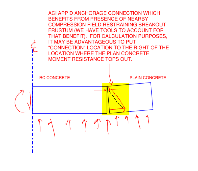
2) As shown below, I view the condition at the rebar cutoff as being a connection rather than either reinforced concrete or plain concrete. The good news with that is that, in my opinion, the typical reinforced concrete detailing requirements don't strictly apply. The bad news is that you've got a connection that needs designing.

3) In many situations like this, I find that the best option is to just replace the footing. Obviously, the viability of that depends on the state of construction at the time the problem is being considered.

4) I'm not a huge fan of doweling in new bars. Given the limited cover, the length of embedment usually required, and access difficulties, I worry that the bottom of the footing will wind up spalling and the finished condition will be worse than what you started with.
C01_bkwnty.png
 
KootK said:
What are the plan dimensions of your footing here and what is the dimension of the unreinforced bit?
It's pretty substantial. Hasn't been poured (well at the time it hadn't been poured. They already added new rebar and poured), but rebar is on site.
In general - good points. Especially the anchorage idea. Makes sense.


Status
Not open for further replies.

Part and Inventory Search

Sponsor