sticksandtriangles
Structural
- Apr 7, 2015
- 494
I am trying to gain some experience for diaphragm design and actually run some numbers.
I am getting intimate with Terry Malone's book and have a good feel for what to do in simple cases (simple span stuff). Ran some numbers on his simple example problems was able to match his answers.
I feel confident that now I can tackle my projects complicated rigid diaphragm with a multitude of lateral resisting elements per level (/sarcasm).
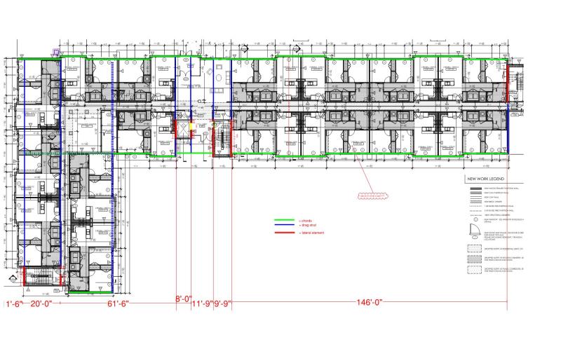
I layout my drag struts and chords. (CMU walls as lateral elements)
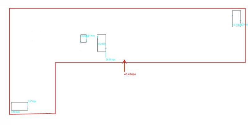
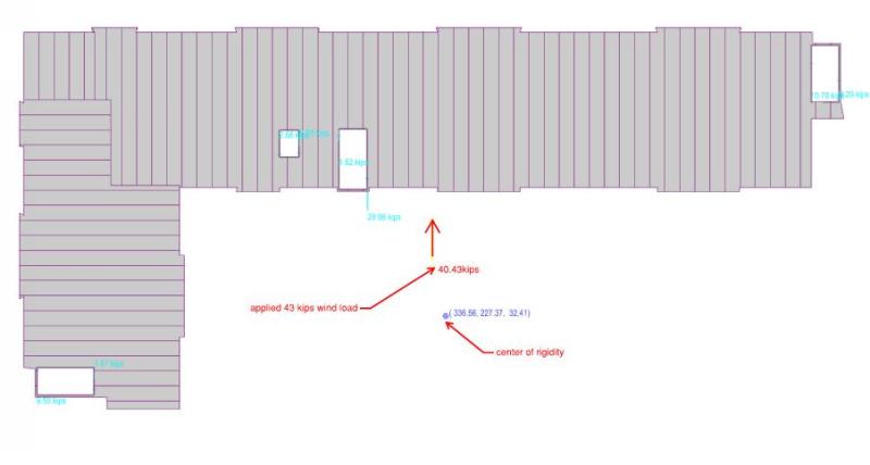
I go to my sturcutral model (using RAM strutral systems) and look at wind load in the y direction. Cool, I find applied loadings and shear reactions in my shear walls. Total wind load of ~40 kips with sum of reaction be =40 kips. Model utilizes the rigid diaphragm assumption
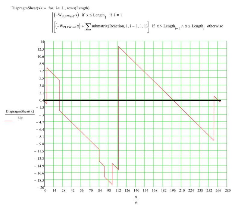
I begin to dig in and draw my shear diagram for my diaphragm... nice... goes to 0 on both ends (with the assumption of a linear plf applied to edge of the diaphragm ~140plf).
Next I draw my moment diagram... NOT NICE does not go to 0 on both end.
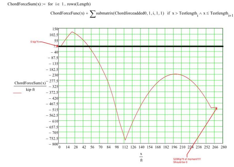
I am in horror as to what I see... how can this be...
I then call over an experienced engineer to ask what is going on and he mentions that he expected the diagram to not go to 0. I was ignoring the torsion effects due to the center of rigidity of the diaphragm not = the center of the applied load.
I check my model. They do not align.
I go to look at my forces in the x direction and sure enough they are large enough that I would not want to ignore them when looking at loading page up and down (sum to be 0 though which is good).
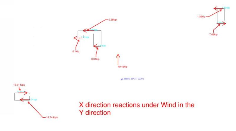
Gut feel... this feels odd. Why do these forces effect my diaphragm moment diagram? Shouldn't my moment at the end of my diaphragm go to 0?
Do you guys have good way to explain what is going on?
A lost engineer.
Thanks in advance for advice.
S&T
I am getting intimate with Terry Malone's book and have a good feel for what to do in simple cases (simple span stuff). Ran some numbers on his simple example problems was able to match his answers.
I feel confident that now I can tackle my projects complicated rigid diaphragm with a multitude of lateral resisting elements per level (/sarcasm).
I layout my drag struts and chords. (CMU walls as lateral elements)

I go to my sturcutral model (using RAM strutral systems) and look at wind load in the y direction. Cool, I find applied loadings and shear reactions in my shear walls. Total wind load of ~40 kips with sum of reaction be =40 kips. Model utilizes the rigid diaphragm assumption

I begin to dig in and draw my shear diagram for my diaphragm... nice... goes to 0 on both ends (with the assumption of a linear plf applied to edge of the diaphragm ~140plf).

Next I draw my moment diagram... NOT NICE does not go to 0 on both end.

I am in horror as to what I see... how can this be...
I then call over an experienced engineer to ask what is going on and he mentions that he expected the diagram to not go to 0. I was ignoring the torsion effects due to the center of rigidity of the diaphragm not = the center of the applied load.
I check my model. They do not align.

I go to look at my forces in the x direction and sure enough they are large enough that I would not want to ignore them when looking at loading page up and down (sum to be 0 though which is good).

Gut feel... this feels odd. Why do these forces effect my diaphragm moment diagram? Shouldn't my moment at the end of my diaphragm go to 0?
Do you guys have good way to explain what is going on?
A lost engineer.
Thanks in advance for advice.
S&T

