Continue to Site

Eng-Tips is the largest engineering community on the Internet

Intelligent Work Forums for Engineering Professionals

  • Congratulations SDETERS on being selected by the Eng-Tips community for having the most helpful posts in the forums last week. Way to Go!

Diaphragm Design - Troubles and Woes

Status
Not open for further replies.

sticksandtriangles

Structural
Apr 7, 2015
494
I am trying to gain some experience for diaphragm design and actually run some numbers.
I am getting intimate with Terry Malone's book and have a good feel for what to do in simple cases (simple span stuff). Ran some numbers on his simple example problems was able to match his answers.

I feel confident that now I can tackle my projects complicated rigid diaphragm with a multitude of lateral resisting elements per level (/sarcasm).

I layout my drag struts and chords. (CMU walls as lateral elements)
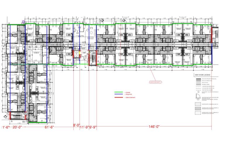
layout_buepl9.jpg


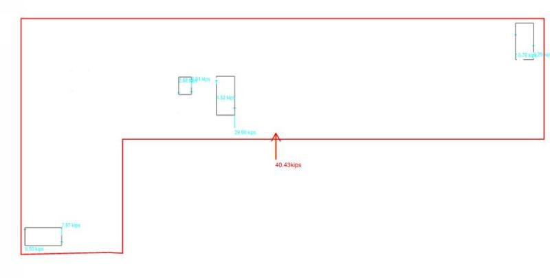
I go to my sturcutral model (using RAM strutral systems) and look at wind load in the y direction. Cool, I find applied loadings and shear reactions in my shear walls. Total wind load of ~40 kips with sum of reaction be =40 kips. Model utilizes the rigid diaphragm assumption
Applied_Loading_mvk1cq.jpg


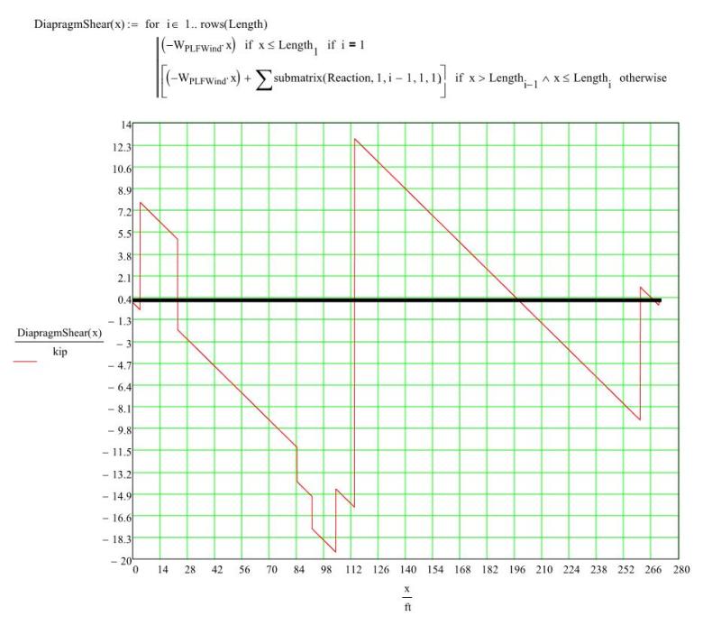
I begin to dig in and draw my shear diagram for my diaphragm... nice... goes to 0 on both ends (with the assumption of a linear plf applied to edge of the diaphragm ~140plf).
Shear_Picture_hvenyz.jpg


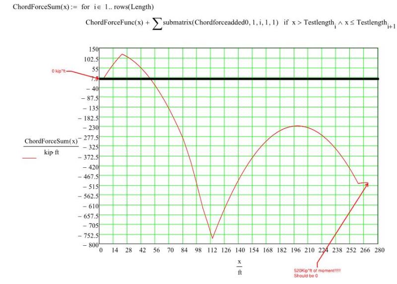
Next I draw my moment diagram... NOT NICE does not go to 0 on both end.
Moment_Picture_hfyhos.jpg


I am in horror as to what I see... how can this be...

I then call over an experienced engineer to ask what is going on and he mentions that he expected the diagram to not go to 0. I was ignoring the torsion effects due to the center of rigidity of the diaphragm not = the center of the applied load.
I check my model. They do not align.
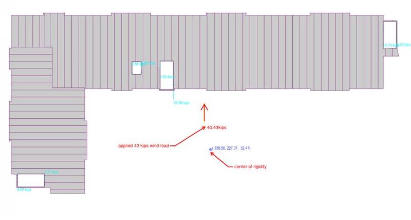
Center_of_rigidity_lq5th1.jpg


I go to look at my forces in the x direction and sure enough they are large enough that I would not want to ignore them when looking at loading page up and down (sum to be 0 though which is good).
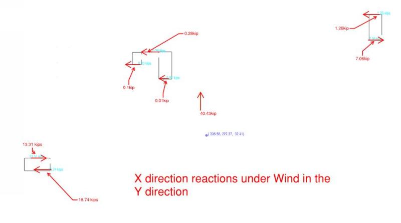
X_direction_aw7ipc.jpg


Gut feel... this feels odd. Why do these forces effect my diaphragm moment diagram? Shouldn't my moment at the end of my diaphragm go to 0?
Do you guys have good way to explain what is going on?

A lost engineer.

Thanks in advance for advice.
S&T
 
Replies continue below

Recommended for you

It should go to zero but may have to be corrected to get there. Root around figure 6.5 of this doc and see if that's your issue: Link. If it is, it's a consequence of the finite depth of the "beam" when loads come in via the parallel to span edges (as oppposed to typical line element approximation).

I like to debate structural engineering theory -- a lot. If I challenge you on something, know that I'm doing so because I respect your opinion enough to either change it or adopt it.
 
The X direction reactions seem off at the far right and far left shear walls. The diaphragm is expected to rotate clockwise due to torsion. I would expect the X direction reactions to vary linearly with distance from the center of rigidity. The reactions at the far right and left shear walls are opposing each other and vary greatly, which seems like possibly a modeling error.
 
The moment diaphragm does not close in your model because part of the torsional moment is resisted by the orthogonal walls. This moment needs to be added back into the diaphragm to satisfy equilibrium. The document KootK linked to provides a few methods for doing this.

To prove this to yourself, try running your model with all orthogonal walls removed. Then the torsional moment will be resisted entirely by the walls parallel to the load, and the moment diagram should close.

Your shaft walls appear to be resisting torsion as closed sections, hence the opposing forces. If you were to disconnect the shaft walls (model as 4 independent walls) you would get a force distribution more like bhiggins described.
 
Thanks all.

Kootk, thanks for the post. I believe I will do some form of moment correction as outlined in the link you posted.

I also felt a little skeptical about the magnitude of the torsional forces that RAM was spitting out in the bottom left of the building. I will dig into that.

 
Just to close the loop, got it to go zero using the reference KootK linked.
Moment_Picture_Revised_xzipdh.jpg

Now onto the more difficult stuff haha.
 
It may be correct... but I can't help but stare at how your Y direction wind reactions at the bottom left core wall act in opposing directions. Is there really that much torsion in that core from this floor?

Also, shouldn't your shear diaphragm's first reaction from the left then add to the magnitude of the shear instead of subtracting from it? I may be mistakenly reading your reaction diagram...
 
I agree with your sentiments atrizzy. I can not figure out why there is so much torsion in that shaft at the bottom left. I double checked stiffness and material properties and it is the same as the other shafts. It is also an "open" shape (door openings excluded from shaft) so there should not be much torsional rigidity in the open shaft... I am at a loss for why it is reacting the way it is.
 
If I was you I'd try removing the long walls of the bottom left shaft and run it to see what it does.
 
I feel the closed shapes of the left and right stair cores are creating a pseudo end fixity for your diaphragm- the diaphragm is no longer behaving as a pin-pin "beam" but as a beam having rotational springs at each end. There are relatively few shear walls in this design which appears to be amplifying this effect greatly. If you had 2-4 more "Y" shear walls I believe this effect wouldn't be as pronounced.
 
Am I the only one here who would idealize this as a 2 span continuous beam and analyze/design it that way?
 
Are you removing only the door openings in your model or the segments above the openings as well? If removing only the door openings you don't have a true open section and all four walls in your shaft wall assembly will resist torsion as an assembly (in addition to each wall resisting torsion based on its in-plane stiffness and distance from the center of rigidity). Looking at the shaft on the left side of your plan, it seems like this is occurring since both x and y walls have opposing forces. Also keep in mind that channel-shaped wall assemblies will have torsional forces in the flanges when load is applied away from the shear center of the wall assembly. Again, these torsional forces are in addition to each wall resisting torsion based on its in-plane stiffness and distance from the center of rigidity.

Basically, diaphragm force distribution to composite wall assemblies is incredibly complex, especially when you add wall openings. The best reference I've found for doing this type of analysis is J.R. Benjamin's Statically Indeterminate Structures. But if your goal is just to practice doing rigid diaphragm design and perhaps have a shot at verifying the force distribution determined by the software, I would make it easy on yourself and disconnect the wall segments so that they don't behave as composite assemblies.
 
Status
Not open for further replies.

Part and Inventory Search

Sponsor