Hello,
We are working on a job where the customer wants to use a diaphragm gasket. This is something that I am not familiar with, and I am trying to figure out how this will work within the scope of the ASME VIII-1 App.2 flange design rules.
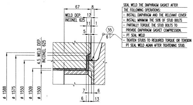
This gasket will be used in a heat exchanger between a channel body flange and flat cover. Our customer has provided a detail from a different vessel to illustrate the joint configuration:

A few descriptions of what you're looking at:
[ul]
[li]The heavy body on the left of the image is the channel body flange, complete with an internal weld overlay (Inconel 625)[/li]
[li]The diaphragm gasket is the 6mm thk plate on the right side, that thickens to 13mm at the OD. It is welded to the channel body flange weld overlay material with a 6mm fillet weld.[/li]
[li]The blind flange is on the far right side, flush with the diaphragm gasket. It is not welded to the diaphragm gasket.[/li]
[/ul]
Most of this makes sense to me, but I am trying to justify in my head what values for m and y I should use in the ASME VIII-1 App.2 calculations for the channel body flange. In one sense, this looks like a flat plate, where I would use the following values from ASME:

On the other hand, this gasket is seal welded to the body flange. In that sense, the ability for the gasket to seal would not be dependent on gasket seating. With this thought process, I'm thinking that perhaps I should set m and y to equal zero.
Does anyone have experience with diaphragm gaskets, and what values would you use for m and y?
Thank you,
We are working on a job where the customer wants to use a diaphragm gasket. This is something that I am not familiar with, and I am trying to figure out how this will work within the scope of the ASME VIII-1 App.2 flange design rules.
This gasket will be used in a heat exchanger between a channel body flange and flat cover. Our customer has provided a detail from a different vessel to illustrate the joint configuration:

A few descriptions of what you're looking at:
[ul]
[li]The heavy body on the left of the image is the channel body flange, complete with an internal weld overlay (Inconel 625)[/li]
[li]The diaphragm gasket is the 6mm thk plate on the right side, that thickens to 13mm at the OD. It is welded to the channel body flange weld overlay material with a 6mm fillet weld.[/li]
[li]The blind flange is on the far right side, flush with the diaphragm gasket. It is not welded to the diaphragm gasket.[/li]
[/ul]
Most of this makes sense to me, but I am trying to justify in my head what values for m and y I should use in the ASME VIII-1 App.2 calculations for the channel body flange. In one sense, this looks like a flat plate, where I would use the following values from ASME:

On the other hand, this gasket is seal welded to the body flange. In that sense, the ability for the gasket to seal would not be dependent on gasket seating. With this thought process, I'm thinking that perhaps I should set m and y to equal zero.
Does anyone have experience with diaphragm gaskets, and what values would you use for m and y?
Thank you,
