Eng-Tips is the largest engineering community on the Internet

Intelligent Work Forums for Engineering Professionals

  • Congratulations waross on being selected by the Tek-Tips community for having the most helpful posts in the forums last week. Way to Go!

Different braced lenghts for outer and inner flanges... in SAP2000

Status
Not open for further replies.

X4vier

Civil/Environmental
Feb 24, 2018
152
0
0
CO
Hello,
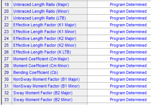
I want to discuss the correct configuration of braced lengths in SAP2000 for a spandrel beam used to support a CMU wall.
Spandrel_CMU_crprfz.png

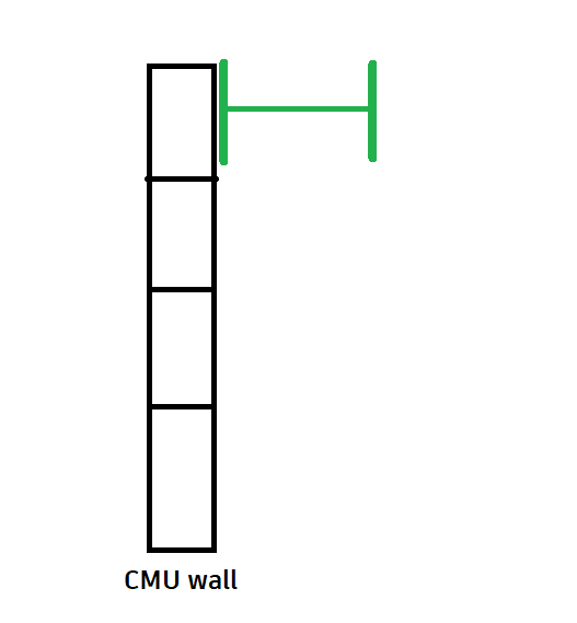
What I think is that the CMU causes the outer flange to be braced so the minor axis would also be braced, but the inner flange is unbraced so the lateral torsional bucking would be unbraced.
Are correct those assumptions?
Thanks.
 
Replies continue below

Recommended for you

This is an interesting question, and I am curious to see what others think. The CMU braces the outer flange, yes. But I don't think this means the minor axis is braced. The lateral torsional bucking won't be an issue assuming lateral forces are taken by the WF-beam and the CMU full restraints the outer flange. Which I assume is the case based on the beam's orientation,
 
If the CMU has suction the inner flange will have compression. That's what I said LTB is unbraced.
Remembering the parameters in SAP2000.
Lengths_s7jjd2.png
 
I believe there is a specialized form of buckling that can apply in these cases. It is described in AISC design guide #25 (Tapered member design). Though I believe it applies to non-tapered members as well.

I know we called it CAT, but I believe this stands for "constrained axis torsional" buckling. This is a compressive failure (IIRC). But, you might take a look at that design guide to see if there is any modification to flexural strengths based on CAT limits for axial strengths.
 
In my opinion, the left side flange is braced for LTB, right side flange is not.
In the weak axis, the wall supports the section and you have no bending.
If you have an axial load, Lx = L, Ly = 0, Lz = L, and as Josh pointed out, constrained axis torsional buckling may control (see AISC commentary).

If you really want to get into the weeds, the right side flange may be checked for LTB with Lu = L, and Cb = 2.
This is a similar condition to roof purlins in uplift (Cb = 2 as pointed out in AISC commentary).
 
That CAT "constrained axis torsional" buckling implies that spandrel can't be modeled correctly on SAP2000 or you see any combination of parameters that can work.
 
If the loading is reversible than it seems like it cant be worse than Lb = total length between supports. Basically saying neglect the restraint due to anchorage at CMU wall.
 
You can check by hand, if CAT governs over strong axis buckling, which it probably will.
I would find whatever unbraced length in Ly or Lz that gives equivalent results to the CAT strength, assuming CAT governs.

Then input that unbraced length into SAP, so that your column strength reflects the CAT unbraced
 
Status
Not open for further replies.
Back
Top