Continue to Site

Eng-Tips is the largest engineering community on the Internet

Intelligent Work Forums for Engineering Professionals

  • Congratulations IDS on being selected by the Eng-Tips community for having the most helpful posts in the forums last week. Way to Go!

Difficulties creating mesh!

Status
Not open for further replies.

M MOTAAL

Structural
Aug 22, 2018
22
Greetings, I have a simple model in which I am trying to simulate single lap joint of two cold formed sheets (represented as solid elements)connected through a screw (self drilling screw).
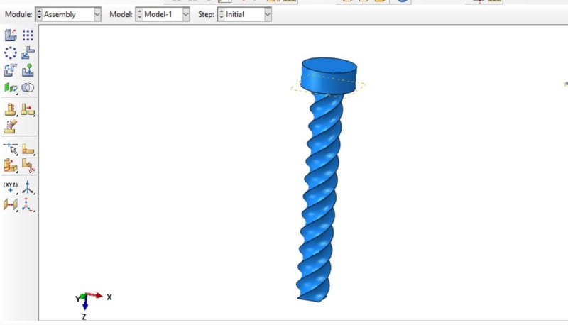
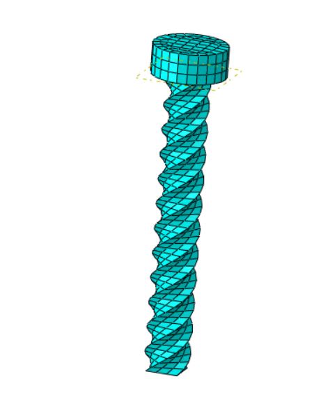
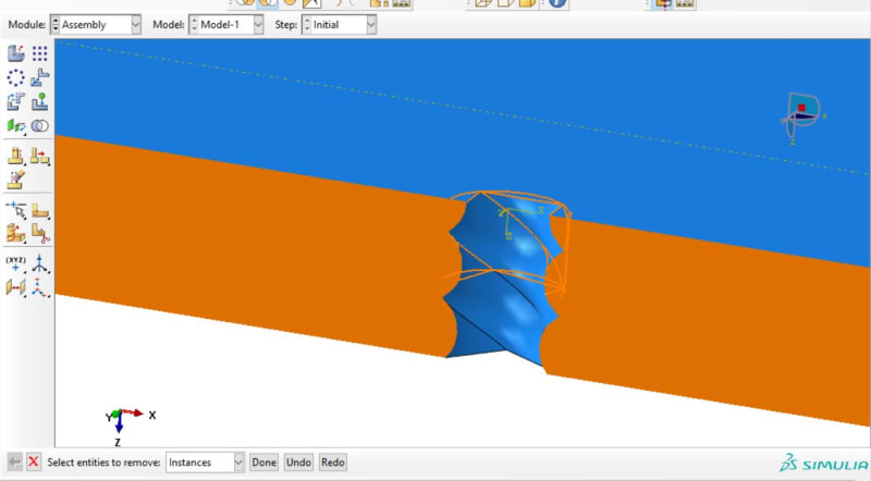
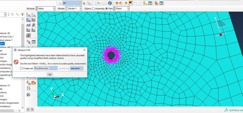
I have managed to draw the screw with the threads and also managed to mesh the screw in addition to creating grooves of the self drilling screws in the both sheets, and have meshed the screw well but the issue is with the mesh of the grooves in the sheets. They have many troubles in generating their elements without errors. Up to the moment I have been not able to mesh it properly despite of applying many and different strategies including different arrangement of partitions to isolate the region with troubles to deal with apart from the rest of the plates. I wish if someone has the experience dealing with such complex geometry to advice me and spot the light on any trick that can help me efficiently mesh the plates. the model is attached below.
Thank you in advance.
 
 https://files.engineering.com/getfile.aspx?folder=a6d92dbc-96d5-48bf-96aa-2a7a439fa5f0&file=Screw_Lap.cae
Replies continue below

Recommended for you

Is it absolutely necessary to include thread in your model ? In most cases of bolt joint analyses threads are omitted because they are too complex and even if you mesh them correctly, they increase the number of DOFs a lot. There are other ways of modeling bolts and they still can be very accurate. In the newest (2019) version of Abaqus they even introduced enhanced bolt contact capability in Abaqus/Standard that can be used to include the presence of thread without actually modeling and meshing it. But if you still want to include thread geometry in your simulation it will be necessary to make some partitions.

Apart from attached .cae file could you also attach some images showing your geometry and mesh with errors ?
 
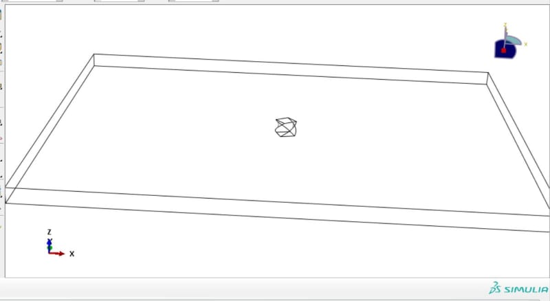
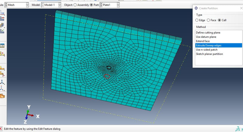
Thank FEA way for fast response again ...In fact this joint is a very simple part of a bigger model I will try to solve within the few next weeks. In this large model I will expected to show a full connection details and FE analysis to that connection which includes 34 screws in the same manner of the simple lab joint. I need to study the effect of the threads to this problem. the larger model will be explicitly solved by LS Dyna but after exporting all of its data and mesh details from ABAQUS to LS Dyna as a ".bdf" or Nastran input file that can be exported from abaqus to LS Dyna easily and can be read in LS Dyna by return. I wish the images below can describe the situation. Thank you again.
Screw_fzw0ab.jpg
Screw_Mesh_vffqtj.jpg
Sec_lgwaij.jpg
Wire_Framed_Plate_gbhfaw.jpg
Partionning_with_aids_of_wire_shape_qawcvz.jpg
Mesh_Error_sg3neg.jpg
 
For the plate I think that the only option to obtain usable mesh is to separate small cylindrical region around the hole and mesh it with tetrahedral elements. Then you can create tie constraint between this region and the remaining part of the plate to avoid problems with non-matching meshes. This thread is even worse than in case of regular bolts since it has curved edges and thus can't be meshed with hexahedral elements.
 
I actually did...but LS-Dyna has some issues dealing with C3D10 elements generated with the tetrahedral meshing technique... I appreciate your help. If there is any way to avoid these tetrahedral elements my problem is gone ... do you have any other tricks to deal with this matter.


I even thought of Hyper Mesh software as an option but still the problem related to the C3D10 solid elements. By the way the treads of the screw itself are meshed with structured technique and hexahedral elements ...the way I maintained the threading in the plates was by subtracting or cutting a screw instance from the plate then adding another screw in stead of the one used in generating the threads surface in the plates.
 
Maybe different type of tetrahedral element will work in LS-Dyna (there are several kinds available). It's hard to say which one will be compatible in that software. You could also try to mesh this in some external mesher (since Abaqus is not so good in meshing) and then export to Abaqus and LS-Dyna. Maybe other type of elements in Hypermesh will work. This software is probably the best for meshing.

However if you still want to try meshing this thread with hexahedrons in Abaqus, try further partitioning it and reducing element size significantly.

If everything else fails bottom-up meshing is an option to consider.
 
I don't see a major problem. In the plate use a larger radius for the partition of the center region. Partition the outer area of the plate to get four portions. Mesh the inside with tets and the area around with hex. A/CAE will automatically tell you, that it ties the incompatible meshes together. No need for the user to add the tie manually.
 
 https://files.engineering.com/getfile.aspx?folder=99a21319-5e46-4962-981a-23ef009add9c&file=SNAG-0185.png
Status
Not open for further replies.

Part and Inventory Search

Sponsor