Hello everyone!
I am struggling a little bit with the input data for 3-W transformer when it comes to Digsilent my purpose is to study only symetrical short circuit. Have anyone some experience with that?
My input:
_______________________________________________
Sn MVA 5,2
Un1 (HV) kV 11
Un2 (MV) kV 1,657
Un3 (LV) kV 1,658
I A 272,9
I A 905,9
I A 905,4
Tap pos. (-)
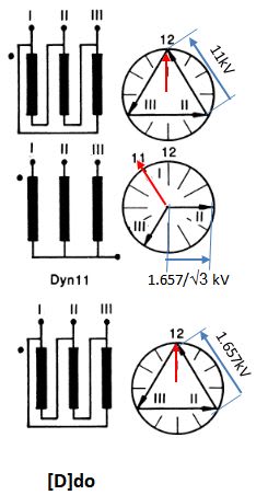
Connection (-) D(-7,5°)yn11d0
Short cir. Resistance (1-2) % 1,00%
Short cir. Reactance (1-2) % 9,95%
Short cir. Resistance (1-3) % 1,00%
Short cir. Reactance (1-3) % 9,95%
Short cir. Resistance (2-3) % 2,50%
Short cir. Reactance (2-3) % 15,40%
inrush current xIn 5x
_________________________________________
So based on this I have calculated the Sn for each winding (HV - 5,2 MVA, LV - 2,6 MVA, MV - 2,6 MVA)
My question is how to enter the positive sequence impedance (if via calculated copper losses + calculated usc% or with the uk% and re(uk))
and the second how to input this phase shift (-7,5°) - I got an an constant error to this.
Thank you very much in advance for any help! I really don´t know what to do :/

