First let me preface this by stating that I am a mechanical engineer not an electrical engineer. I have some basic knowledge of electronics so hopefully we can communicate in the same language to resolve this ")
I have a 12V LED module (only has two leads for power and gnd) and when I took apart the module it turns out that it has its own programmable controller inside (running at 5V) that uses mosfets inside to flash the LEDs in programmed patterns, but it has no method of dimming the LEDs (it has a bunch of other components for vreg for the controller, current limiting resistors for the LEDs etc). Before taking apart the module I thought perhaps I could PWM the 12V power and dim the LEDs but I no longer see this working as I will likely just be rapidly turning the programmable controller on and off very quickly and messing with the flashing patterns.
So that brings me to this post.
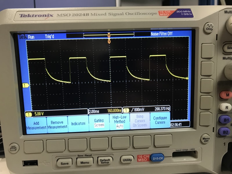
Although the module nominal input is 12V, when I drop the input voltage using my power supply, there is no appreciable difference in perceived brightness down to 9V (current also drops from ~190mA to ~100mA). Below 9V I would estimate a 50% brightness drop when lowering input voltage to ~8.2V (current drops to ~25mA)
So I have some 1n4002 diodes here and I believe on the datasheet it shows a forward voltage drop of 0.6-0.8V with current between 0.03A to 1A. If it put one in series with the LED module and run it at 9V I achieve the ~50% dimming I am looking for (voltage across the LED module should be in the ballpark of the 8.2V I'm assuming). If I used a ~30ohm resister in series instead of the diode I get roughly the same result as I am limiting the current.
Here in lies my first question, by using a diode in series to drop the voltage, or using a resistor to further limit the current (since it already has resistors built into the module) what is the advantage or disadvantage to either solution?
Second question, someone suggested to use a constant current LED driver to dim the LEDs but this was before determining all of the other components inside the module. I'm not sure what effect it would have trying to "push" a constant amount of current through the module with everything else going on in there (programmable controller etc.)
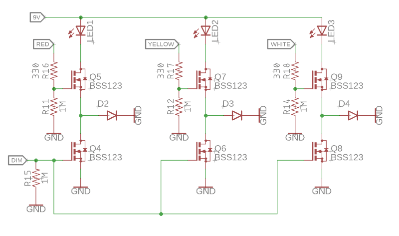
Third question, I actually have three of these LED modules in red, amber, white... which I would like to control individually (on/off). The brightness of all LED modules can all be tied together as I have no reason to run them at a different brightness simultaneously. I came up with the following circuit (see attached) using MOSFETS for the ON/OFF and controlling the dimming with the diode as mentioned in my first question above to achieve two discrete brightness levels. The red/yellow/white inputs from my controller would be normally low to turn off the lights, and then driven high to turn each of the colors on. A common dimming signal would be driven high so that path to GND avoids the diodes (or resistors, see question 1). Low signal on this line would put the diode/resistor in series to dim the lights. Does this look like it should work, or is there a better way to do it with less components?
Thank you all for your patience with all of my questions... there are definitely some gaps to fill in my fundamental understanding of electronics.
I have a 12V LED module (only has two leads for power and gnd) and when I took apart the module it turns out that it has its own programmable controller inside (running at 5V) that uses mosfets inside to flash the LEDs in programmed patterns, but it has no method of dimming the LEDs (it has a bunch of other components for vreg for the controller, current limiting resistors for the LEDs etc). Before taking apart the module I thought perhaps I could PWM the 12V power and dim the LEDs but I no longer see this working as I will likely just be rapidly turning the programmable controller on and off very quickly and messing with the flashing patterns.
So that brings me to this post.
Although the module nominal input is 12V, when I drop the input voltage using my power supply, there is no appreciable difference in perceived brightness down to 9V (current also drops from ~190mA to ~100mA). Below 9V I would estimate a 50% brightness drop when lowering input voltage to ~8.2V (current drops to ~25mA)
So I have some 1n4002 diodes here and I believe on the datasheet it shows a forward voltage drop of 0.6-0.8V with current between 0.03A to 1A. If it put one in series with the LED module and run it at 9V I achieve the ~50% dimming I am looking for (voltage across the LED module should be in the ballpark of the 8.2V I'm assuming). If I used a ~30ohm resister in series instead of the diode I get roughly the same result as I am limiting the current.
Here in lies my first question, by using a diode in series to drop the voltage, or using a resistor to further limit the current (since it already has resistors built into the module) what is the advantage or disadvantage to either solution?
Second question, someone suggested to use a constant current LED driver to dim the LEDs but this was before determining all of the other components inside the module. I'm not sure what effect it would have trying to "push" a constant amount of current through the module with everything else going on in there (programmable controller etc.)
Third question, I actually have three of these LED modules in red, amber, white... which I would like to control individually (on/off). The brightness of all LED modules can all be tied together as I have no reason to run them at a different brightness simultaneously. I came up with the following circuit (see attached) using MOSFETS for the ON/OFF and controlling the dimming with the diode as mentioned in my first question above to achieve two discrete brightness levels. The red/yellow/white inputs from my controller would be normally low to turn off the lights, and then driven high to turn each of the colors on. A common dimming signal would be driven high so that path to GND avoids the diodes (or resistors, see question 1). Low signal on this line would put the diode/resistor in series to dim the lights. Does this look like it should work, or is there a better way to do it with less components?
Thank you all for your patience with all of my questions... there are definitely some gaps to fill in my fundamental understanding of electronics.
![[ponder]](/data/assets/smilies/ponder.gif "[ponder] [ponder]")