Continue to Site

Eng-Tips is the largest engineering community on the Internet

Intelligent Work Forums for Engineering Professionals

  • Congratulations KootK on being selected by the Eng-Tips community for having the most helpful posts in the forums last week. Way to Go!

Directional valve problem 2

Status
Not open for further replies.

lukin1977

Mechanical
Jan 19, 2009
397
Please help me solve a problem in a double acting cylinder system

The system is very simple. An oil pump, a directional valve (manually operated ) and the cylinder

Normal operation: valve position es moved by hand (lever) to forward or reverse and the cylinder moves accordingly. One can release the lever at any of those position and the valve stays in it

Problem: Valve is put in forward, cylinder moves forward
valve is put in reverse and the cylinder moves reveres but the operator has to strongly hold the lever because if he release the lever the valve position goes back to forward and so the cylinder goes forward too

Hope my explanation is clear

According to your experience, what is the problem? Internal wear of the directional valve? What should we do?
 
Replies continue below

Recommended for you

Sounds like an issue with excessive flow forces acting on the spool due to flow intensification.

Would need to know pump flow, cylinder bore & rod dimensions & valve size/flow rating to confirm.
 
Is the valve equipped with a return spring? Does it have detents to hold the valve in one position or the other?

Ted
 
Check the directional valve if it has an return spring inside, as well as the cylinder internal. Sine no detail tubing layout, how the oil flow around the cylinder sections?
 
A picture of the distributor would have been appreciated.
I think you have a somewhat high back pressure in return T and that the O-ring seal between this T and the chamber of the centering spring of the spool is bad.
Do you have an external leakage from the spring housing (opposite side of the lever)?
Do you have another distributor in series for another function on this machine? In this case there may be a poor connection of the return lines.
Therefore check that there is no oil in the spring chamber. If yes: disassemble the spool and replace the O-ring.
 
Bumblyari: I do not have all those value right bow but the system has been working for more than 10 years with same configuration

hydtools: there is no return spring on the valve and there are no dents to hold position either

mk3223: no return spring on spool or cylinder. cylinder is 320mm bore and 1000mm length (internal)

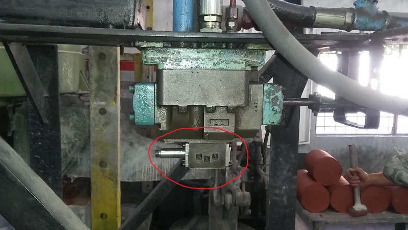
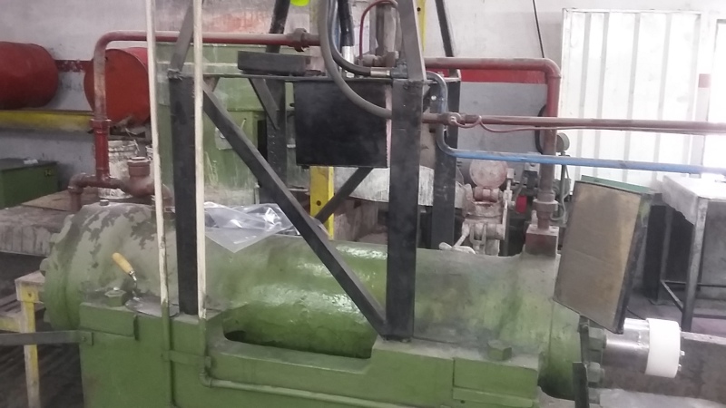
picture attached. what is the little valve below (circle in red)?

20170522_130922_gzhzv5.jpg
 
Without knowing the full history of the setup and just going on the picture...

The small valve is the pilot valve that once operated the main valve. Someone has converted a pilot operated valve to a manually operated valve.

Much more data is required to diagnose your problem.

It could be that main valve spool is being affected by the flow forces of oil coming from the cylinder, but looking at the valve size, it is doubtful.

The pilot valve is single operation, just one solenoid that would have sat on top of the silver barrel. It is possible that your tank line is seeing high pressure and that high pressure is being fed to end of the main spool, via the pilot valve. That will push the spool and it may be why you are seeing the this issue.

I know you say that it's worked this way for 10 years, but if the tank line is blocked or if a return line filter if blocked, the pressure will increase in the tank line.

On the assumption that the pilot valve connects its A or B port to tank, where the tank pressure increases, it could over ride the manual signal and push the spool.

Lots of assumptions, hence we need more data. A picture of the underside of the valves would be good.[pre][/pre]
 
Without a diagram of the hydraulic oil flow for your system, I can only give a guess. Is the oil fluid cycling back from the cylinder to some where?
Question: is it a " plugged connection" at the left of the valve in the "red circle"? And, what's it for?
 
I'm guessing the pilot valve solenoid failed and was disconnected long ago,
and now its return spring has failed also, so it's fighting the manual
operator on the main spool.

Or something else.

Mike Halloran
Pembroke Pines, FL, USA
 
Your valve started life as a spring-offset two-stage solenoid operated valve. The little valve circled in red is the solenoid pilot valve which has had its solenoid removed. It then looks like one end cap has been modified to convert the main stage of the valve to manual operation. However, the spring offset pilot valve will still be directing pilot pressure to one end of the main spool continuously hence the reason it is difficult to move the spool in one direction.

You could do a bit more modification to the valve to overcome this then wait for a disaster to happen or you could buy and fit a valve that is designed to be manually operated. It's a standard interface so they are readily available.
 
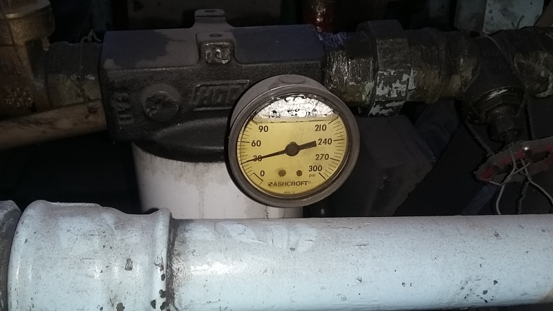
I forgot to tell you that there is an inline return filter on the return line to the tank and it has a pressure gauge.
Return line pressure is 30 psi, which is low to us, we change the filter once pressure has reach 40 psi. The filter change is done every 3 months approximately

I am thinking the the pilot valve lever has been move for some reason and that is what is causing the problem. Could this be?

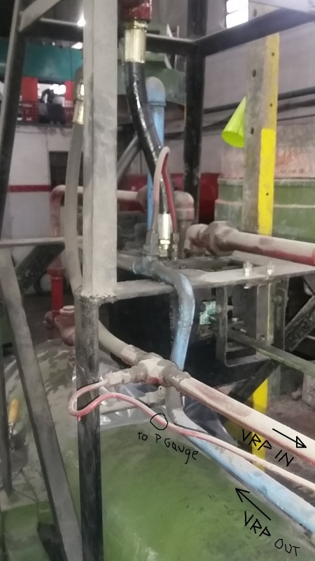
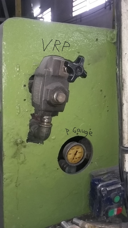
VRP: Pressure Regulation Valve (manually operated). It is used to regulate the force of the cylinder on the forward stroke

I will do my best to make a drawing of the installation tomorrow. I dont have time now

20170522_115151_cwiakr.jpg


20170522_151848_qvd79m.jpg


20170522_151834_kbfh2h.jpg


20170522_151858_u60l8l.jpg


20170522_151907_zhtahc.jpg
 
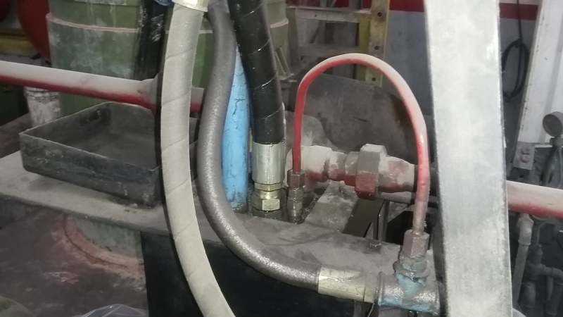
The directional valve is inside the black box
 
First thing to do is remove the pipework and replace it with tubing and fittings that are rated for the pressure in that system.

Assuming your gauge reads 2/3 of the full scale, you see 3000 PSI. The malleable fittings that I can see in the photos are only rated a maximum of 600 PSI.

I'm not going to be complicit in this. That system is dangerous if you are working it above 600 PSI, and that is again assuming that the fittings are heavy duty and not rated to just 200 PSI.

See link


HPost:

Red pipes are the high pressure side and they are all rated for 3000 psi. Relief valve is set to 2000 psi
Working pressure is 800 to 1500 psi

Ligh blue pipes is the return line. Rated to 600 psi, Is it to much of a trouble to ask you to show me in one of the pictures what are the fitting your are referring because now I am worry too
 
Look at the fitting under the valve you have labelled VRP...

The welded fitting is a dead giveaway. The elbow is also clearly a low pressure fitting.

Who told you that the red pipes are rated to 3000 PSI?

You need to research Class 150 and Class 300 malleable iron fittings to see the difference in the pressure ratings and also the difference in appearance.


A question off-topic: If a system is to work at a certain max pressure, does every pipe and fitting of the system must be size according to max pressure or the system can be separate in high and low pressure (return lines) and pipes accordingly?
 
It's a question of risk of failure.

Components such as valves, pumps, hoses, tubing and fittings all have a pressure rating. That rating is equal to the maximum normal working pressure of the part of the system in which they work.

It's perfectly acceptable to have plastic tubing on return lines, as long as the working pressure does not exceed the strength of the material or the joints.

It's also common for some components to be occasionally operated above their rated pressure for short periods of time. However, they have to have been validated to work at that pressure. The duration and frequency at the higher pressures also need to be confirmed as part of a histogram or an operating profile.

Volume production or standard items such as the above fittings will have type approval for the design and the pressure rating. All parts made to the standard will be suitable to run at the design pressure. Production variations mean that some parts can withstand higher pressures.

Rupture of pipe, tubes or fittings cause the release of high pressure hydrocarbons. It's not a pleasant experience and it should be avoided.
 
You could remove all annotated components with a star in the small pilot distributor.
Find out how they were mounted because if this change does not work it will have to be reassembled.
And if it works you can throw these components in the trash.
 
 http://files.engineering.com/getfile.aspx?folder=59f594dc-d2f8-4388-9cd2-658ec8582611&file=NG6_-ATOS.pdf
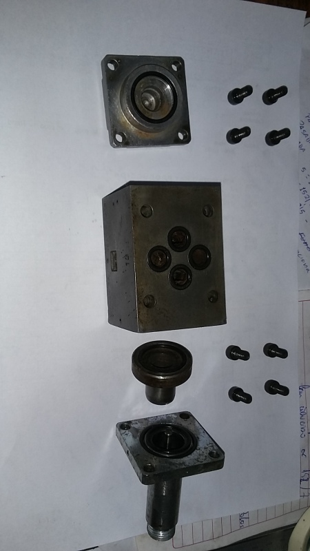
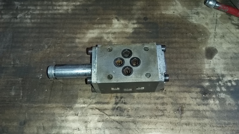
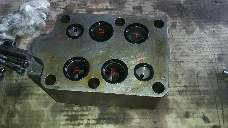
directional and pilot valve are dismounted for inspection and cleaning. We found that the pilot valve has been modified (like you said) long time ago. Pilot valve spool is missing (see picture)

We are about to reassemble the whole thing and test

What are ports X and Y for at directional valve?

20170529_105253_wdgmac.jpg


20170529_103845_z7mxne.jpg


20170529_103939_npfpd9.jpg
 
Status
Not open for further replies.

Part and Inventory Search

Sponsor