Eng-Tips is the largest engineering community on the Internet

Intelligent Work Forums for Engineering Professionals

  • Congratulations waross on being selected by the Tek-Tips community for having the most helpful posts in the forums last week. Way to Go!

Directly toleranced radius with a "located" center, ASME Y14.5-2018 4

Status
Not open for further replies.

Burunduk

Mechanical
May 2, 2019
2,335
0
0
IL
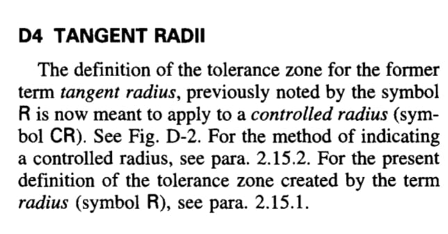
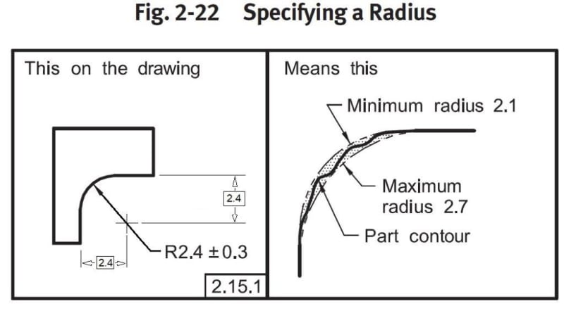
One of the changes from the 2009 to the 2018 version of Y14.5, is the interpretation of the tolerance zone of a radius dimension with a direct tolerance.
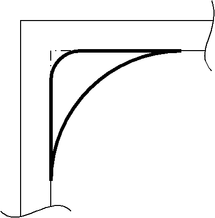
According to 5.16.1 (page 39), the problematic crescent shaped tolerance zone from the previous versions is still intact, but only when the center of the radius "is not located". The new thing is - "When the center of the radius is located via dimension(s), the arcs are concentric". No example is shown for the new definition.

Does anyone here know or understand the reasoning behind this change and how the new scheme with the located/dimensioned center is to be implemented correctly? Is the idea here to establish some sort of true center on which the tolerance zone arcs are based? If so, is this another case for basic dimensions unrelated to a geometric tolerance? Does this become sort of a profile tolerance that controls both the form and the location of the actual radius feature, only without explicit datum references? Alternatively, does it not control location and only change the shape of the tolerance zone? If so, would reference dimensions for center location be appropriate?
 
Replies continue below

Recommended for you

Burunduk,

I had no idea that this change had been made ;^). It's hard to say what the intent was, with no example (or even a definition of what type of dimension are used to locate the center. Unfortunately they seem to have taken a non-rigorous definition and added more non-rigor to it.

The Y14.5 meetings are coming up later this month - I'll see if I can find out anything.

Evan Janeshewski

Axymetrix Quality Engineering Inc.
 
I'm guessing that the reasoning comes from the definition of a radius itself: if the center is located via "hard" numbers, then all possible radii must be concentric/coaxial by definition.
But if the center is not located, then the intent is that the arc is meant to blend smoothly with adjacent sides of the part's outline. Thus the ends of the tolerance zones are to meet, making the arcs not concentric.

John-Paul Belanger
Certified Sr. GD&T Professional
Geometric Learning Systems
 
John-Paul,
So do you understand those "hard numbers" for locating the center to be basic dimensions?
The problem I have with such "hard" location is that it essentially turns the directly toleranced radius dimension into a location control, additionally to controlling the arc form (radius value).
But as we know, a location control is usually only meaningful if datum references are used, because one needs a rigorous reference system from which to locate.
Also I think that a location controlling +/- tolerance is in contradiction to the policy of the standard and the tendency in the two recent versions.
 
It didn't change; they clarified the difference. Same interpretation as ever.

Retaining any +/- tolerance is in "contradiction," but they still keep those.

Yeah, sure. rigorous reference system. Write it up and submit the proposed change. It won't be settled here.
 
3DDave,
The interpretation for the tolerance zone of a radius with a direct tolerance was always a crescent shape. There was never a different interpretation. The basis for it is alignment to the tangent features. This is the measurement principle when using measurement devices such as radius gages or optical comparators.

Nothing was "clarified". Rather, the concept got muddled up even more.

What about the cases in which CAD models are part of the product definition to replace basic dimensions on minimally dimensioned drawings?
Does this make all radius centers "located" and changes the tolerance zone from the default shape?
 
It's not a complaint but a question.
It is also not 'my' personal problem.
And before I submit a change request to reverse something that was deliberately incorporated into the latest version of the standard, it makes sense to investigate what the intent was. Evan indicated that he is willing to query this in the upcoming committee meetings, so this is already a positive outcome.
 
"The interpretation for the tolerance zone of a radius with a direct tolerance was always a crescent shape."

This was only required for the "CR" (controlled radius.) They also showed it for a non-CR fillet radius, but didn't use "crescent" to describe it.

They gave examples only for non-located radii in '2009 and '1994, though one is supposed to rely on the words and not the pictures and the words say "A radius symbol, R, creates a zone defined by two arcs (the minimum and maximum radii)" which seems clear.

Perhaps the interpretation of located radii was considered so obvious obvious that no one felt the need to give an example.

Here's my prediction - housekeeping. Someone thought that the last 100+ years of concentric limits for a located, directly toleranced radius needed to be explicitly described because they had gone to all the trouble of describing, in the standard, located directly toleranced radii since the 1960s.

Please draw an example of how one might generate a crescent shape for a located radius with a direct tolerance.

The more interesting question to ask is why a located radius cannot be a controlled radius. More housekeeping. There are so many loose threads to choose from.
 
"This was only required for the "CR" (controlled radius.) They also showed it for a non-CR fillet radius, but didn't use "crescent" to describe it."

Before the 1994 version, the current definition of 'CR' was the definition of 'R', as described in Appendix D of Y14.5M-1994:

Screenshot_20221006-191325_Drive_u25ko1.jpg


So if anything, the definition that doesn't explicitly specify the crescent shape with arcs tangent to the nearby features is a relatively recent introduction that was not part of the ANSI versions. If you have different information from older standards or drafting manuals, present it. As for the 94' and 09' versions - there is no indication that the tolerance zone for the +/- radius can be formed by concentric arcs.

"Someone thought that the last 100+ years of concentric limits for a located, directly toleranced radius needed to be explicitly described..."

So how do those concentric limits work? What type of dimensions locate the center - are they basic? Is a theoretical (basic) center established as an origin for the tolerance zone arcs, or maybe the actual as produced center of a best-fit fair radius is controlled somehow by a location tolerance, and then used as an origin for the tolerance zone controlling the actual feature?
 
You see, all those special cases that you feel need clarification in the standard - that's a matter to send to the committee. Write it up and submit it.

Please draw an example of how one might generate a crescent shape for a located radius with a direct tolerance. You will need to include that in your change request.

If you do it now Evan can hand-deliver it.

As I wrote and you ignored - crescent only applied to the controlled radius case. Since you are arguing about concentric radii, that has nothing to do with the history of the term crescent. The prior practice didn't mention the crescent, did it?

You are a funny guy. I say "Common practice" and you say "But where is it written down?" Common practice is called common practice because no one wrote it down. Sometimes there is a need to standardize some common practice when it's recognized there are unacceptable variations. It appears that has not been the case for this area of dimensioning and tolerancing, unless you have some experience otherwise to point to. It does not appear that you have.
 
Why am I not surprised that you claim to know that concentric limits for a directly toleranced radius dimension is an undocumented "common practice" that has existed for 100+ years, but when I ask you how this works you have no answers and point elsewhere (to the committee)? I actually made it easy on you and offered two options for application of what you claim to be a common practice. All you needed to do is pick one, and only if neither is right - tell your version of how it should be specified and interpreted. So why didn't pick the right answer or explain how this works? Are you a novice engineer who doesn't know yet? Then you should first learn how things work, then teach history lessons about how long they've been working this way. Obviously, you also didn't provide a typical application example for your 100+ year old "common practice".

As I told you and showed you and you either ignored or didn't understand, the ASME Y14.5M-1994 Appendix D indicates that the only definition that formerly existed for a radius indicated by the R symbol, is what currently describes the Controlled Radius - the same definition that leads to the crescent shape. As I said, if you find this conclusion incorrect, show the source that proves that "the prior practice didn't mention the crescent", or didn't mean crescent.

Here is the drawing example, a modified fig. 2-22 from the 09' standard:
located_R_and_tol_zone_1_xduvoc.jpg

The tolerance zone stays the same as shown, because according to the 2009 version, the basic dimensions that were added do nothing to affect the tolerance zone. Without a basic radius and a profile tolerance, there is no uniform tolerance zone between concentric arcs. Not according to any ASME or ANSI standard prior to 2018, and not according to any common practice.

Draw an internal sharp 90° corner, then fillet it by some radius. Without erasing the radius, draw a smaller radius fillet in the same corner. What shape is formed by the two radii? That's how the variation of a directly toleranced radius dimension works, and the meaning of such tolerance.
 
For a fillet radius. They only felt that explaining a fillet radius was required. The explanation for the figure I gave you is obvious and common practice - it looks like someone decided to do some housekeeping and codify the common practice for non-fillet radius callouts.

Time is going by - get the form and write it up so Evan can take it.

Also, technically, it isn't even a crescent - the shape in the standard has flats and a crescent shape doesn't. Yet again hijacking a word that has a common definition and limiting it to an artificial boundary.
 
Call it whatever you want - crescent, semi-crescent, crescent-like, almost-crescent, sometimes-crescent, pick one you like best or dislike least. In any case, what limits the variation is not two concentric arcs, but two arcs tangent to the surfaces forming the corner.

What applies to fillets also applies to rounds (external radii). Therefore the figure you "gave" me (1-23?) would also generate the same type of tolerance zone had R8 been directly toleranced. Per the 2009 standard or earlier versions, the tolerance zone is two concentric arcs only if the tolerance type is profile (or if someone did something awkward like applying cylindricity to a radius). It is not so when the tolerance is plus-minus or limit dimensioning. Think of how a radius gage would be used on this feature.

You didn't answer whether you are a novice engineer.
If you aren't, you should know that two concentric arcs as a tolerance zone that limits the feature's variation, can contain radii both larger and smaller than the limiting arcs. This would violate the dimensional limits of the radius. Draw it and see for yourself. If you're a novice engineer, not realizing that is forgivable, but you should note that your self-confidence is exaggerated.
 
Status
Not open for further replies.
Back
Top