Continue to Site

Eng-Tips is the largest engineering community on the Internet

Intelligent Work Forums for Engineering Professionals

  • Congratulations KootK on being selected by the Eng-Tips community for having the most helpful posts in the forums last week. Way to Go!

Discontinuous chords in wood framed building @ dormers 3

Status
Not open for further replies.

redtiger

Structural
Oct 10, 2007
8
Hello,

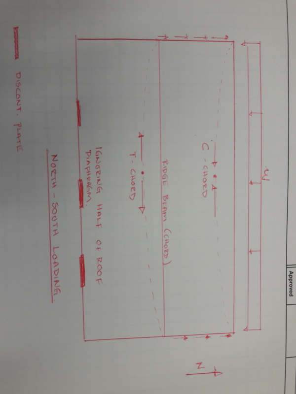
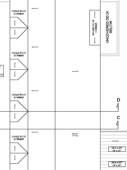
I am working on a new wood framed building. There are several dormers where the double top plate will have a discontinuity. Please see the attached sketch.

ENG_TIPS_vulpwj.jpg


LAYOUT_xwdfrz.jpg


Based on diaphragm design, the chord force is around 2.5 kips. My question is the following, how do I connect the plates at these locations. My first idea was to install a steel frame at these openings, weld a strap to the end of each steel post and nail the other side of the strap to the next continous double plate.

Any other ideas would be greatly appreciate it.

Regards
 
Replies continue below

Recommended for you

Your idea would work mechanically but I doubt it wold be too popular with your framers. Another option is to use those partial height second floor walls as an extension of your roof diaphragm and then designate the plates at the second floor level your chords/collectors. Essentially, this is viewing the partial height, second floor walls similar to the heels of a high heeled roof truss. It's messy but, in these situations, the line between roof and wall diaphragm gets blurry.

I like to debate structural engineering theory -- a lot. If I challenge you on something, know that I'm doing so because I respect your opinion enough to either change it or adopt it.
 
Why wouldn't you just use the ridge beam as the chord and consider the dormer-side half of the roof as not part of the diaphragm (if it works)?


Check out Eng-Tips Forum's Policies here:
faq731-376
 
Another alternative would be to step your chord 4'-3" back up into the roof at the dormers and provide a chord segment there effectively detailed to lap with the wall plates.

I like to debate structural engineering theory -- a lot. If I challenge you on something, know that I'm doing so because I respect your opinion enough to either change it or adopt it.
 
Thank you Kootk, I will explore your second alternative.

Thank you JAE, Im still trying to digest the idea of only using one side of the roof and ridge beam as a chord.

 
JAE, here is a sketch for the diaphragm. I see the ridge beam acting as a chord with the north to south loading. Im having difficulties when I reverse the load. It seems that half of the roof (dormer side) is cantilevered and just goes for a ride north.


20170110_143550_rp07n6.jpg


Regards.
 
OP said:
Im having difficulties when I reverse the load. It seems that half of the roof (dormer side) is cantilevered and just goes for a ride north.

Many engineers would argue that, for E-W load when the function is that of collector rather than chord, the collector does not need to be continuous as a chord does. Yet another shade of grey. What bothers me about the use of a partial diaphragm is that it can imply rather a lot of axial strain in portions of the diaphragm outboard of the chords. This is rough stuff though so I try not to get too up tight.

I like to debate structural engineering theory -- a lot. If I challenge you on something, know that I'm doing so because I respect your opinion enough to either change it or adopt it.
 
Seems that 99% of the houses built have some sort of chord discontinuity that does not get addressed. My feeling is that houses end up functioning like a bunch of attached three-sided structures where chord continuity does not really matter.
 

You have a diaphragm with intermediate offsets (notches). If you are looking for a more in-depth analysis of how to design the transfer wood diaphragms around the notches, check out 'The Analysis of Irregular Shaped Structures - Diaphragms and Shears Walls' by Terry Malone. Most cases only require some additional strapping, blocking, and tighter diaphragm nailing near the notches. I also agree with XR250 that this usually does not get addressed for residential construction.
 
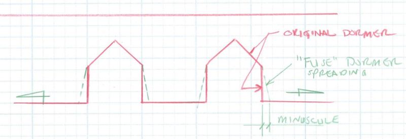
It would seem that for N-S wind the expansion or contraction of the line along the "missing" chord at the dormers wouldn't really be a huge issue in that the dormer interruptions are almost like independent fuses that allow the strain along that line to occur without "tearing" the non-chorded diaphragm areas.

Check out Eng-Tips Forum's Policies here:
faq731-376
 
JAE said:
It would seem that for N-S wind the expansion or contraction of the line along the "missing" chord at the dormers wouldn't really be a huge issue in that the dormer interruptions are almost like independent fuses that allow the strain along that line to occur without "tearing" the non-chorded diaphragm areas.

While I agree that it's almost certainly not a huge issue, or even a small one (I'm with XR philosophically), the fuse concept doesn't ring true to me. First off, you usually want a fuse to be ductile. Secondly, I think that the mechanically correct way to look at strain on the un-chorded side of the diaphragm would be something like this:

1) Estimate curvature based on the properties of the chorded, structural diaphragm.

2) Project the curvature from #1 out to the unchorded edge to estimate strain there.

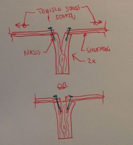
3) Look at what the strain at the unchorded edge means for sheathing joints in flexural tension where the fastening would tend to split the supporting framing perpendicular to grain.

Designated or not, you're likely to have unintended chord out at the "non-chorded" edge, between dormers, whether you want it or not. Therefore:

1) sheathing tensile strain surely is not a problem between dormers.

2) Any real potential for strain incompatibility issues would surely arise at the "notches" created by the dormers. And that could be detailed accordingly.

Just as nac521 proposed essentially.


I like to debate structural engineering theory -- a lot. If I challenge you on something, know that I'm doing so because I respect your opinion enough to either change it or adopt it.
 
It is not even a small issue really.

For a 3 story wood framed building - maximum preferred lateral drift is perhaps L/400.... (3 stories)(12 ft/story x 12"/ft)(1/400) = +/- 1 inch.

You would design your half-diaphragm then to limit the lateral drift (at the outer eave) to 1"... (i.e. no extension out to the edge is necessary since you are back-calculating the drift at the edge to begin with.)

A 1" deflection in a longer diaphragm - say 60 ft long - would not amount to much strain along the eaves....think a 60 ft. long arch with a 1" offset.

The dormers are "open" so any spread in their sidewalls would be quite minuscule.

We're talking wood framing here - very ductile.

Check out Eng-Tips Forum's Policies here:
faq731-376
 
JAE said:
It is not even a small issue really.

Agreed. Just theoretical sport worrying.

JAE said:
For a 3 story wood framed building - maximum preferred lateral drift is perhaps L/400.... (3 stories)(12 ft/story x 12"/ft)(1/400) = +/- 1 inch.

JAE said:
you would design your half-diaphragm then to limit the lateral drift (at the outer eave) to 1"..

But drift is not strain. For example, with the same diaphragm center line deflection, a deeper diaphragm will have more strain. So while half diaphragm drift and eave drift may be the same, half diaphragm chord strain and eave strain will not. The eve strain will be amplified.

JAE said:
(i.e. no extension out to the edge is necessary since you are back-calculating the drift at the edge to begin with.)

There`s no need to project out to the eave if drift is your only concern. However, as I explained above, strain is another kettle of fish and the projection to the eve would be necessary in order to work it out.

JAE said:
A 1" deflection in a longer diaphragm - say 60 ft long - would not amount to much strain along the eaves....think a 60 ft. long arch with a 1" offset

And there`s the rub. It`s a one inch offset at the diaphragm center line. If your 60ft diaphragm were 40ft deep, the offset that matters would be 241" as it pertains to in-plane diaphragm strain at the eves.

JAE said:
The dormers are "open" so any spread in their sidewalls would be quite minuscule.

Agreed. My concern, if I really had one, would not be the sidewalls but, rather, the integrity of the diaphragm immediately surrounding the "notch". Particularly the re-entrant corners. Rationally, it's another solid argument for some offset chord elements there for reinforcing.

JAE said:
We're talking wood framing here - very ductile.

In what sense are you thinking? As I understand it, the overwhelming majority of wood members and connections fail via some permutation of brittle tensile fracture. It's just the nature of an imperfection riddled materiel. The main exception that I'm aware of is diaphragm performance due to fastener slip. The in-plane diaphragm strain that I envision is shown below and, certainly, very little ductility could be expected there.

Font_yltotd.jpg


I like to debate structural engineering theory -- a lot. If I challenge you on something, know that I'm doing so because I respect your opinion enough to either change it or adopt it.
 
Hmmm...not sure you are getting my drift :)

Kootk said:
But drift is not strain. For example, with the same diaphragm center line deflection, a deeper diaphragm will have more strain. So while half diaphragm drift and eave drift may be the same, half diaphragm chord strain and eave strain will not. The eve strain will be amplified.
The 1" drift is at the outer edge of the building - depth of diaphragm doesn't matter.
You would design your diaphragm to limit the building drift (I haven't even talked about shear wall deflection so your actual diaphragm deflection would be really, even less.
From that you back calculate the diaphragm deflection from the limit of drift at diaphragm midspan. So whatever depth of diaphragm you have - be it 12 feet or 12000 feet, the arc of the outer edge of the diaphragm is still just 1" or so and the strain in the diaphragm is still based on the difference in length of the straight diaphragm eave line and the arc length of the deflected diaphragm. Hoooke's Law forever.

The sketch you show assumes that the strain is all concentrated at some brittle connection where in reality you have all sorts of fuses along the line....think about the additional deflection we add to our shear wall deflections due to nail slippage. Also the dormers are giving up a huge amount of stiffness through the length so any possible build up of strain will be simply lost in the dormers.

A 3" lateral diaphragm deflection on a 100 ft. long diaphragm eave results in a net gain in arc length of 1/64" approximately.
The strain from that is very small (1.3 x 10^-5). Waste of time to even bother with it.
You would still have double top plates, continuous blocking or a collector of sorts along the edges between the dormers to help pull the thing together where it can - but the strain is nothing.

Junk_qddkwc.jpg


Check out Eng-Tips Forum's Policies here:
faq731-376
 
I think I would create a drag line at the top of the dormers with strapping and blocking, then take the force beside the dormer openings to the shear walls below through the shorter intermediate roof diaphragms...

Mike McCann, PE, SE (WA)


JAE said:
Hmmm...not sure you are getting my drift

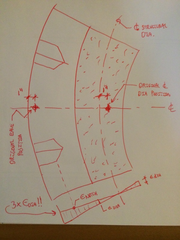
Nope, still kicking up dust. Please review the sketch below, in particular the details of the strain diagram at the bottom.

JAE said:
The 1" drift is at the outer edge of the building - depth of diaphragm doesn't matter.

As I see it, per the sketch below, eave strain will be 3X peak structural diaphragm strain precisely because of the width of the outstanding diaphragm.

JAE said:
You would design your diaphragm to limit the building drift...From that you back calculate the diaphragm deflection from the limit of drift at diaphragm midspan.

There's nothing to back calculate. Per the sketch below, the magnitude of the drift at the eave will be identical to the magnitude of the drift at the structural diaphragm center line. It's the strain that will differ.

JAE said:
So whatever depth of diaphragm you have - be it 12 feet or 12000 feet, the arc of the outer edge of the diaphragm is still just 1" or so and the strain in the diaphragm is still based on the difference in length of the straight diaphragm eave line and the arc length of the deflected diaphragm.
.

Again, I believe this to be your fundamental source of error. The arc formed by the 1" displacement is only part of the story. The far ends of the eave also spread further apart which add more axial strain. Vastly more. This is quite analogous to, say, reinforcing a wide flage beam with a WT on the bottom. The WT isn't just displaced downwards, it's stretched. And that composite stretching is the source of our VQ/I stuff.

JAE said:
The sketch you show assumes that the strain is all concentrated at some brittle connection where in reality you have all sorts of fuses along the line....think about the additional deflection we add to our shear wall deflections due to nail slippage.

And what would these fuses be? All I see is some axially stiff sheathing panels and some nailed joints. Do you really think that you'll get meaningful nail plowing action through the plywood prior to the tension perpendicular to grain failures that I illustrated above? I don't.

JAE said:
Also the dormers are giving up a huge amount of stiffness through the length so any possible build up of strain will be simply lost in the dormers.

The eave strain between dormers will be unaffected by the presence of the dormers. Eave strain at any location in the non-structural diaphragm will simply be a linear amplification of the strain in the structural diaphragm as I've shown below. And the structural diaphragm isn't notched.

JAE said:
A 3" lateral diaphragm deflection on a 100 ft. long diaphragm eave results in a net gain in arc length of 1/64" approximately. The strain from that is very small (1.3 x 10^-5). Waste of time to even bother with it.

I'd be happy to play along but we'd have to assign a width to this diaphragm in order to calculate meaningful results, for the reasons mentioned above.

Rationally, I feel that one must acknowledge the presence of meaningful strain at the edges of diaphragms. For that strain is also the strain in our diaphragm chords. So if there's not meaningful strain in our diaphragm chords, how do our chord forces come about? 1/64" in 100 ft is a strain of 0.00015. That's not going to generate any chord force.

JAE said:
You would still have double top plates, continuous blocking or a collector of sorts along the edges between the dormers to help pull the thing together where it can - but the strain is nothing.

I acknowledged these practical realities myself in my previous post (11 Jan 17 19:28). Logically, however, I don't think that they should be included in the current, theoretical discussion. It seems patently inconsistent to follow this path:

1) Design a partial diaphragm to avoid the complexity of dealing with at notched full diaphragm.

2) Ignore the problematic aspects of the partial diaphragm because we actually have a notched full diaphragm.

2017-01-12_14.51.08_wmwzgb.jpg


I like to debate structural engineering theory -- a lot. If I challenge you on something, know that I'm doing so because I respect your opinion enough to either change it or adopt it.
 
Your sketch assumes flexural deflection. Diaphragms have significant shear deflections so that 3x rotation, and your sketch, isn't all that meaningful or correct.

"there's nothing to back-calculate"..... that isn't true. You START with a limit on lateral drift for your building. You include in that deflection the shear deformation caused drift and also include any diaphragm deformation that adds to drift between shear walls. If you START with L/400....or L/360 or whatever, you have a limit as to how much deflection you can tolerate in your diaphragm at its midspan.

Even with your not-correct flexurally deformed diaphragm, you'd still work backwards to find a half-roof diaphragm stiffness that would limit that arc. I use the term back-calculating to suggest that you'd start with the limit on deflection and then back-determine the necessary diaphragm stiffness to accomplish that.

For a usual range of 3-story wood framed buildings, that drift limit really minimizes the resulting arc length of the eave edge.
Wood is a very VERY forgiving material in construction and the use of a half diaphragm in this particular case, just isn't that big of a concern. I've even done this on other designs and with no problems.

As you mentioned..."1/64" in 100 ft is a strain of 0.00015. That's not going to generate any chord force."

What Mike says above, adding a collector of sorts to the top of the dormers, could be considered as well...just more cost and to accomplish what, though.


Check out Eng-Tips Forum's Policies here:
faq731-376
 
JAE:

You could think of the strapping and blocking as a continuous top plate - just relocated to the point where the roof diaphragm wants to tear. From that lone, the forces travel down the sloping roof diaphragm that can be considered a sloping shear wall, all to the vertical shear walls below.

A little over the top, but it works...

Mike McCann, PE, SE (WA)


Depending on the aspect ratios and % of solid diaphragm vs former conditions I would add the straps Mike mentioned and design the pieces of the diaphragm as a notched diaphragm in the spirit of Terry Malone.

If the notched diaphragm can't calculate because the dormers take out too much area I'd try and develop some collector / continuity across the dormers with "transfer columns" strapped at roof diaphragm and dormers to tie discontinuities together.

This all assumes high seismic forces.
 
jdgengineer - I think you have a point about seismic...there perhaps would be a bit more concern about the behavior of the "non-diaphragm" side of the roof...I was mainly thinking about wind here.

Check out Eng-Tips Forum's Policies here:
faq731-376
 
Status
Not open for further replies.

Part and Inventory Search

Sponsor