Eng-Tips is the largest engineering community on the Internet

Intelligent Work Forums for Engineering Professionals

Distributed electrical current 1

Status
Not open for further replies.

lucky-guesser

Industrial
Apr 11, 2023
94
0
0
US
Screenshot_2023-05-08_100746_p1lgoa.png


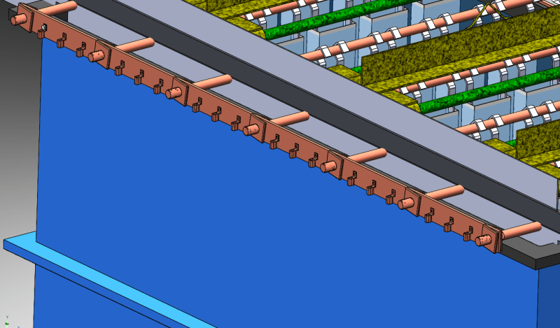
Hello all, I am designing the copper bussing (see attached concept image) for a new zinc plating tank to be built by an outside supplier who specializes in tank building. We are trying to minimize cost as much as we can so we are building the tank to have more electrical capacity than we should actually need but we don't want to overbuild more than necessary, copper is expensive and we are already over budget. The issue I'm having with the tank company is a disagreement over the size of the bus bar that ties our anodes together.

Our current tank is rated for 1500 amps, and the current bus bar is 1/4 x 2, and using the traditional wisdom of 1000amp/in^2, that would mean that this bar is only good for 500 amps. The reason we can get away with this (in my opinion) is because we have 18 wires spread across this bar, going to 7 different anodes, so the amperage is spread out and no one cross section actually sees that full 1500 amps. We have had no heat issues in the past, I would say the current bar is very close to if not room temp, so there is no build up.

We are building the new tank to be good up to 2000 amps, and what the manufacturer is wanting us to do is use a 1/2x4 bar (2000amp). I have the new bus bar drawn up as 3/8x3 (1,125 amp) which should already be scaled up more than enough for no more than we are increasing the tank rating.

Question is, is there some obscure electrical property that I am unaware of that would cause the bus bar to actually see full load at a given point? I wouldn't think so considering how small our current one is that hasn't caused any issues but with how much push back we are getting I figured I should do some investigating. Our current design is fairly unorthodox compared to the designs that this company usually works with so I am thinking that they may just be stuck in the mindset they usually have where the full load is coming in from one end and not distributed like in our case.
 
Replies continue below

Recommended for you

Assuming a feed from one end only and an equal current distribution, 1500A / 18 = 83.3 Amps per wire.
The current from the supply end;
to the 1 st wire = 1500 Amps
to the 2 st wire = 1417 Amps
to the 3 st wire = 1333 Amps
to the 4 st wire = 1250 Amps
to the 5 st wire = 1167 Amps
to the 6 st wire = 1083 Amps
to the 7 st wire = 1000 Amps
to the 8 st wire = 917 Amps
etc.
You are at about the 14th wire out of 18 before the current drops to the rated 500 Amps.
What are the implications of running greater than rated current through the bus bar?
The bus will run much hotter with three times rated current.
There will be a noticeable voltage drop from end to end of the bar.
This voltage drop will be measurable, but will it be important?
You tell us.Is there a noticeable difference between the plating thickness from one end of the tank to the other?

Suggestions:
As the current is dropping along the length of the bus, you may step down the size of the bus as the current drops.
If you are using this approach, be wary, as the voltage drop at the end may be greater and may degrade the work at the far end of the bus.
Connections; Supply cables and connectors bolted directly to the bus will be subject to temperatures higher than they are rated for.
That may lead to insulation damage and/or heat corrosion damage to the connecting hardware.
Suggestion: use a short piece of bus suitable for 500 Amps per square inch as a transition between the supply cables and the bus.
Feed from the bottom so that you get a little cooling from convection.
OR Thinking outside the box:
I would investigate the economics of multiple feeds.
If you used the original sized bus, nominally good for 500 Amps and fed it in four places, your maximum current density will be 500 Amps but the overall capacity will be 2000 Amps.
You will use more copper for your supply cables but much less copper for the bus bars.
Alternately you could feed the 1/4" x 2" bars in three places for a maximum current of 667 Amps. That is only 133% above rated rather than your original 300%
Two feeds (At the quarter points rather than the ends) and your maximum current will still be less than your present tank.
Let us know how it works out.

--------------------
Ohm's law
Not just a good idea;
It's the LAW!
 
waross, that's exactly what I'm saying, we have 18 separate feed wires all spread across the bus bar like you suggest, and plan to do that again on the new one. That's why I don't understand the concern from the manufacturer.
 
Are the wires feeding the bus or is the bus feeding the wires?
With one supply connection to the bus, some of the bus will be taking the full current.
Each section of bus between wires must considered as a separate circuit for current.
You can't average, but you may arrange alternate feeds.

--------------------
Ohm's law
Not just a good idea;
It's the LAW!
 
where the full load is coming in from one end and not distributed like in our case.
Switch-gear, MCCs, Bus-Duct, there are a lot of common bus applications where the load is distributed along the length of the bus.

--------------------
Ohm's law
Not just a good idea;
It's the LAW!
 
Lucky Guesser said:
we have 18 separate feed wires all spread across the bus bar
But the current that goes to the feed wires has to come from somewhere. Where does the main power source to the tank get connected?
 
18 wires feed the bus bar, the currents goes a few inches through the bus bar to the nearest anode (the cylindrical shape in the pic), then on down the system. At no point is the current funneled through one point.
 
Got it.
Incoming current arrives through those 18 little objects that look like coffee cups (six groups of three each).
Outgoing current (to process) through those seven round bars, more or less equally spaced along the bus.
Total process current draw = 1500 A.

Assumption #1: balanced current on load side, 1500/7 = 214 Amp per bar.
Assumption #2: balanced current on incoming conductors, 1500/18 = 83.3 amp per conductor.

This means that the bus bar will see a current of 214 A between rightmost bar and first "conductor" connection - even though the conductor is only providing 83.3.
Between second conductor and end bar, bus will see (214 - 83) = 131 A.
Between third conductor and end bar, bus will see (131 - 83) = 48 A.
Between third conductor and SECOND bar in from right, the remainder of conductor 3 current flows (83 - 48) = 35 A.

And so on. Max current density through bus at any point (assuming no failure of incoming or outgoing conductors) is 214 / (0.25 * 2) = 428 A/in2.

Converting energy to motion for more than half a century
 
I will defer to your greater insite, Gr8blu.
I missed those connectors.
If you are going to use longer anodes, you should upsize your bus.
If you are simply going to add more anodes, the original bus is fine, but add more supply wires.

--------------------
Ohm's law
Not just a good idea;
It's the LAW!
 
Status
Not open for further replies.
Back
Top