Hello Peers,
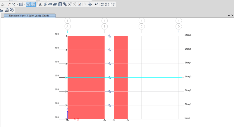
I am struggling to make sense of ETABs results for interacting concrete shear walls. I have the following ETABS Model:

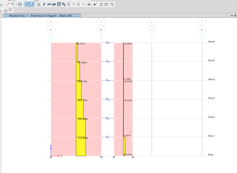
Two cantilever shear walls with pinned bases connected with a rigid link (to simulate a concrete floor with no coupling force, could also be done by assigning diaphragms). I get the following shear outputs from ETABs.

Based on conventional shear theory (shear distributed by stiffness, i.e. 2nd moment of inertia) there should be a linear increase of shear in each of the walls (backed up in pg 381 of Paulay and Priestley). However, from ETABs, the shear in each wall varies. I suspect this is due to some coupling action which I have not accounted for, or due to the deflected shape. However, I'm abit worried regarding how much this differs from conventional theory.
Anyone care to shed some light?
Regards,
Joey
I am struggling to make sense of ETABs results for interacting concrete shear walls. I have the following ETABS Model:

Two cantilever shear walls with pinned bases connected with a rigid link (to simulate a concrete floor with no coupling force, could also be done by assigning diaphragms). I get the following shear outputs from ETABs.

Based on conventional shear theory (shear distributed by stiffness, i.e. 2nd moment of inertia) there should be a linear increase of shear in each of the walls (backed up in pg 381 of Paulay and Priestley). However, from ETABs, the shear in each wall varies. I suspect this is due to some coupling action which I have not accounted for, or due to the deflected shape. However, I'm abit worried regarding how much this differs from conventional theory.
Anyone care to shed some light?
Regards,
Joey
