Eng-Tips is the largest engineering community on the Internet

Intelligent Work Forums for Engineering Professionals

  • Congratulations waross on being selected by the Tek-Tips community for having the most helpful posts in the forums last week. Way to Go!

Do Bolts Transfer Compression Loads?

Status
Not open for further replies.

Burner2k

Aerospace
Jun 13, 2015
193
0
0
IN
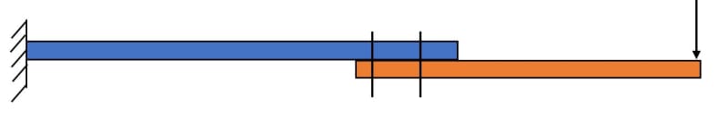
Lets say I have a structure with loading as shown in the below figure.

01_nsvc9y.jpg


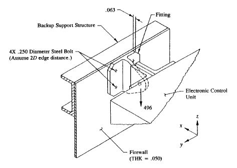
My understanding is along the line of what Flabel says in his book. I am posting excerpt from Chap. 5 "Shear & Tension Clip Supports" Example 5-6, Page 349-350.

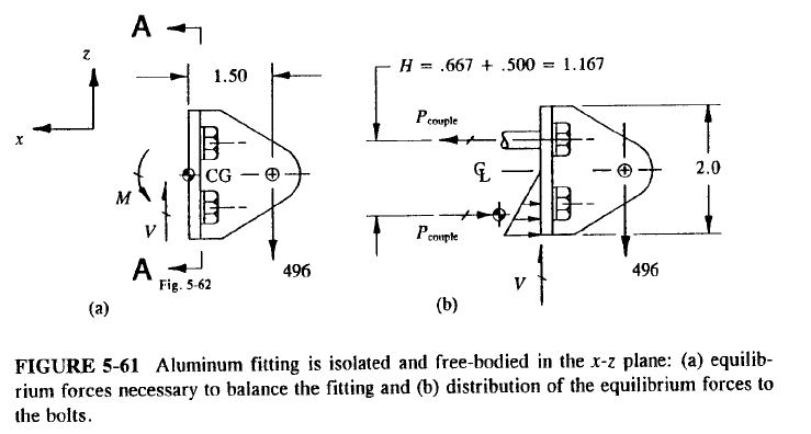
The bending Moment M determined there (that is, at the centroid of the fastener pattern) is further distributed as a horizontal couple-force between the upper bolt attachments and the lower base flange portion of the bracket: one force acting along the centreline of the upper bolts and the other acting along the center of bearing pressure of the lower base flange, as shown below. The contact stresses depicted in this figure are referred to as bearing stresses, not bolt compression forces. Hence, the lower bolts do not actually carry this load. Here, the bearing stresses are entirely carried by the lower base flange.

Image illustrating the FBD as Flabel draws it.

03_iwboye.jpg


A couple of days ago, I was asked in an interview a question along the above lines i.e. how best to transfer moments between two structures. Although, I did not think of this joint arrangement, the interviewer brought this up and I guess he was expecting to hear my knowledge about moment load path. Two plates joined by 2 rows of bolts, subjected to an end transverse load.

02_wortwj.jpg


I gave the above answer i.e. the "compression" part of the couple will be transferred through bearing contact of the plates and bolts won't transfer it. He disagreed and I mentioned I got this info from Flabel's book but he did not seem convinced. He maintained that bolt will carry the compression part of the couple and my scenario plays out if there is only one bolt (to carry tension) and the compression part will be carried via "Heel-Toe" effect between plates.

Anyways, I am posting here to get clarity on my understanding. What do folks think about bolt carrying compression in a joint like above? I plan to do a 2D FE analysis with CBUSH Springs (bolts) & Contact between plates some time in the next week to see how FEM reports the load path.

Regards...
 
Replies continue below

Recommended for you

I would suggest the interviewer was wrong (My wife insists I have no tact.). The moment just reduces the tension in the 'back' bolt, and the tension in the front bolt stays the same until the moment exceeds the initial moment resistance. (Don't know if I explained it correctly).

Dik
 
It seems clear to me that in the examples you give it is not possible for the bolts to carry any compression load. They are in tension and/or shear only. Now anchor bolts for a light pole are often in compression where one end is embedded in concrete and the flanged base of the pole is trapped between two nuts. These bolts may or may not be grouted after the pole is installed.

It could be argued that shear loading does cause transverse compression of the bolt due to shear but I've never seen anyone make that argument.
 
Compositepro said:
Now anchor bolts for a light pole are often in compression where one end is embedded in concrete and the flanged base of the pole is trapped between two nuts.
...

Yup, where there is no initial preload.

Dik
 
I agree that the interviewer is possibly not correct ... I can't see the blots in the sketch carrying compression. With preload as a consideration, then there'd be less tension in the bolts but I don't see the bolts in compression (ever).

another day in paradise, or is paradise one day closer ?

FWIW (which ain't much) my wife says (accusingly) that I'm like a Vulcan ... and I reply either "thank you" or "what's wrong with that ?"
 
Folks,
Thanks for the replies. To make it clear, the interviewer was referring to the 3rd sketch (plates connected with two rows of bolts)...NOT the first two images. Rereading my OP, I think there may be a chance of slight confusion about which structure my question refers to.

I hope your replies about bolts not usually carrying compression is based on the 3rd sketch.
 
I think at no time (in usual construction) do bolts carry compression loads ... certainly in none of the sketches given.

another day in paradise, or is paradise one day closer ?
 
Folks,
Thanks for the replies. It makes me happy & sad at the same time. Happy to know that my understanding is not off...sad if I don't hear back from the company just because of the above (& also because I made a comment justifying my understanding). I don't need the job desperately but it was not a bad opportunity.

Anyways, keeping my fingers crossed.
 
OK... whooooaaaa tigers... here’s my take on this problem...

The first illustration shown would be for a 'snug' nut... no substantial pre-torque after joint 'slop was barely removed'.

Let’s assume a practical bolted joint: [4-each] AN4-X bolts with NAS679-4 nuts [0.25-28UNF-3x] [plus washers... cause I like washers]. NOW torque the dry cad plated bolts/nuts 30-to-40-in#.

The compression clamp-up loads will invariably be centered over the bolt/nut/washer foot-prints.

Resultant clamp-up tension load, per fastener installation, is ~1200 to 1600# [simplified calculation per SAE J1701 K=0.2]... so in this case 4800-to-6400# Force clamps the ‘T’ bracket to the beam. Depending on material thickness [stiffness] the bolts will see vertical 125#-shear/bolt [assuming no shear/friction loads in this joint]... and the upper bolts will see an increase of 375#/bolt tension load... well below the threshold loads noted... while the lower bolts will [might] see a decrease in tension [pre-]load of ~[-]375#/bolt... but maybe not.

Alternately for the second example, assuming parallel and lateral 1/4"D bolt spacing of 1.00 inches [4D]... that would amount to 2400-to-3700# clamp-up per inch along the fastener row. Similar rationale applies to this example as applies to the prior example... except the moment load at the 2-row bolted joint is probably dramatically higher... based on scalar geometry of the example...


Regards, Wil Taylor

o Trust - But Verify!
o We believe to be true what we prefer to be true. [Unknown]
o For those who believe, no proof is required; for those who cannot believe, no proof is possible. [variation,Stuart Chase]
o Unfortunately, in science what You 'believe' is irrelevant. ["Orion", Homebuiltairplanes.com forum]
 
WKTaylor... in none of the examples presented do any of the bolts take compression... his initial reaction was correct, and, the interviewer was wrong.

Dik
 
dik...

I think You missed my point.

Bolted joints by definition provide joint clamp-up... obviously to varying degrees. Clamp-up provides an essential compression-preload/stability for off-shear capacity.

This is why in the first and second visual examples, there is a high potential for joint stability and load capacity.... for properly installed bolts [as I noted].

On-the-other-hand, solid driven rivets DO NOT provide joint clamp-up under any reliable circumstance. Joint clamp-up is established prior to fastening by external mechanical devices... clamps, Clecos, etc. After riveting, tension preload thru the rivet is essentially ZERO.

A general rule-of-thumb [ROT, I learned early in my career] is that rivet tension load capacity should [for reliable design] should be NO MORE THAN = [0.10] X [shear rating]... for that solid rivet. Several design manuals I use have NO allowed tensile ratings for rivets [although very old version of those manuals did show low tensile ratings, at one time (+40-years ago)]. This ROT applies to all solid driven rivet alloys... aluminum, monel, A286, Ti-Cb, steel, etc.

Getting back to the examples shown...

I said my piece about the 2-bolted joints styles.

However IF these 2-bolted joints styles were assembled with solid driven rivets, they would be highly unreliable/unsuitable for the loading scenarios shown.... unless the .10X tension load limit was not exceeded.then all-bets would be off-the table, for the reasons many of You noted. AND I would only recommend use in limited load reversal scenarios.

ONE LAST COMMENT.

F-15 [aluminum honeycomb] wing-tips are installed on the wing-structure end-ribs with a single-row of tension head screws, upper/lower surfaces. What a nightmare for stiffness and durability... especially for the high vibration encountered in high AOA buffet.

Visualize the scenario shown in the figure 5-61 or the bolted-plate example... but remove one-row of bolts entirely... and institute a 100% load reversal spectrum. It doesn't matter how robust the single row design is... it is doomed to have a short life.


Regards, Wil Taylor

o Trust - But Verify!
o We believe to be true what we prefer to be true. [Unknown]
o For those who believe, no proof is required; for those who cannot believe, no proof is possible. [variation,Stuart Chase]
o Unfortunately, in science what You 'believe' is irrelevant. ["Orion", Homebuiltairplanes.com forum]
 
WKTaylor said:
Long post

What you are saying is correct.

But that doesn't change the face that in the examples shown, none of the bolts see any compression load- which is the point Dik was making.

Seeing compression load and applying compression load are not the same thing. All bolts in OP's examples see tension and apply compression.
 
Status
Not open for further replies.
Back
Top