Continue to Site

Eng-Tips is the largest engineering community on the Internet

Intelligent Work Forums for Engineering Professionals

  • Congratulations SDETERS on being selected by the Eng-Tips community for having the most helpful posts in the forums last week. Way to Go!

Do you need to calculate linearized equivilant stress on oposite side where there is no peak stress?

Status
Not open for further replies.

DriveMeNuts

Mechanical
May 4, 2018
447
A pad is welded to the outside of a shell. The pad has external loading applied to it. I am trying to correctly find the membrane and bending stresses in the shell at the edge of the pad.

My understanding is that the purpose of Linearization is to remove the peak stress so that membrane and bending components can be found for each element of the stress tensor. Linearization according to ASME VIII Div 2 Annex 5-A is obviously applicable to the end of the stress classification line where the discontinuity (or pad) is.

However, I am wondering how to handle the stress at the other end of the stress classification line (the inside surface of the vessel). As there is no discontinuity or peak stress, is there a need to use the linearised M+B equivilant stress or can you use the "total" equivilant stress.

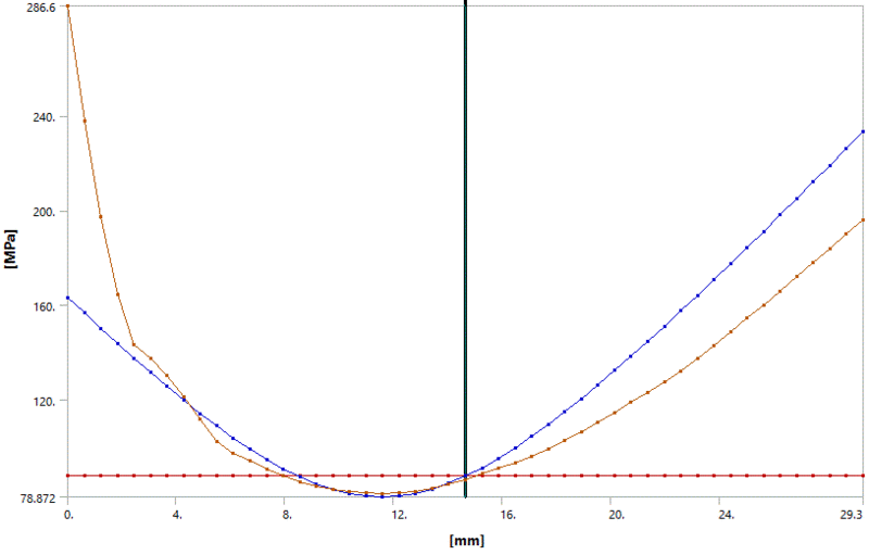
I ask because when linearizing in accordance with Div 2 using ANSYS 19.1 with through thickness bending set to Zero the following plot is the result. The blue membrane plus bending line looks good on the left where the discontinuity is. However it results in an equivilant stress that is 20% higher than the total equivilant stress on the right.
There are 3 stress components: Membrane, Bending and Peak. As there is no peak stress on the right, the blue Membrane Plus bending line should be very close to the brown total stress line. Why is the the blue line 20% higher? It looks like a conservative penalty to me.
Bending_Zero_qknddd.gif


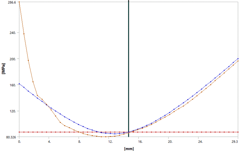
The following graph is for through thickness bending "not" set to Zero. It appears to produce a poorer quality result on the left but a good result that closely matches the total stress on the right.
Bending_non_Zero_zdwy7g.gif


My suspicion is that if I was to model the geometry using shell elements, and apply the Div 2 shell element linearization rules then the stress linearized equivalent stress on the right side would be similar to the second graph, confirming that the extra 20% in the first graph is a penalty. Would I be right?

I guess my question boils down to asking whether there is a need to linearize the stress on the opposite side from a discontinuity where there is no peak stress? If so, the Div 2 linearization rules seem to result in a 20% phantom stress being added to the Von Mises Yield Criteria.
 
Replies continue below

Recommended for you

I don't understand what you are doing: there is no 'linearized stress on the left' or another one 'on the right'. If you plot the through thickness bending stress, you get a straight line going from -σb to +σb; however there is no reason to do so, you just need the value σb at the surface.
Also, if the horizontal brown line is supposed to be the membrane stress, then it doesn't seem to be consistent with the stress distribution.
Be warned, too, that Ansys is not necessarily conforming to Div.2.
My advice is that you read some worked examples of stress linearization.

prex
[URL unfurl="true"]http://www.xcalcs.com[/url] : Online engineering calculations
[URL unfurl="true"]https://www.megamag.it[/url] : Magnetic brakes and launchers for fun rides
[URL unfurl="true"]https://www.levitans.com[/url] : Air bearing pads
 
I share the confusion that prex indicated.

However, this strikes me as a fundamental misunderstanding of the reason behind doing stress linearization, classification, and categorization.

The intent of this process is not to generate a value throughout the thickness, culminating at a M+B on the outside and M+B on the inside. Instead, the purpose is to distill down to a single (or dual) scalar the complex through-thickness stress distribution. At SCL, you will calculate a single membrane value scalar, which itself is calculated from the membrane of each component of the stress tensor. And likewise, you will have a bending scalar, which is calculated from the membrane of each component of the stress tensor, and the bending of the component directions that support valid bending planes - as described in 5-A.4.1.2 Step 2(a) (and yes, I indeed have that reference memorized).

Finally, the linearized stress that you show isn't exactly linear (as in a straight line). But, then again, the intermediate values are meaningless. Please ensure that the components are being properly linearized, and refrain from plotting a "linearized" von Mises stress through the thickness. Such a beast doesn't exist in reality, and ANSYS is doing its clients a disservice by making such a plot available. Stick with the text output.
 
I understand that only the ends of the plots contain meaningful information, although possibly the total equivalent stress is true and accurate throughout as it is taken directly from the FEM results.

The plots have the following linearized normal stress components (They are essentially Principal stresses. Shear is negligible):

Membrane (5-A.4.1.2 Step 1):
X: -25 (X axis is aligned with SCL)
Y: 29
Z: 74

Bending (5-A.4.1.2 Step 2):
X: -36 / 0 (Set to zero in accordance with Div 2 5-A.4.1.2 Step 2(a).
Y: -207
Z: -80

5-A.4.1.2 Step 5 requests the calculation of Von Mises M, M+B(left) and M+B(Right):
Meq = 86 (Von Mises of the Membrane components shown above)

M+Beq(left)
X: -25 -0 = -25
Y: 29 -207 = -178
Z: 74 -80 = -6
Von Mises of M+Beq(left) = 163

M+Beq(right)
X: -25 +0 = -25
Y: 29 +207 = +236
Z: 74 +80 = +154
Von Mises of M+Beq(right) = 231

In the first graph the red membrane line is 86
In the first graph the blue M+B line has values at extreme left and right of 163 and 231 respectively.
These three numbers match up with the graphs.

My delema relates to the "calculated" peak stress on the right side when there isn't a local discontinuity to cause a peak stress.

The graphs show the total stress of and 195 on the right surface. (These are actual equivalent stresses taken from the FEM results.)

The M+Beq stress on the right is greater than the total stress, meaning there is a negative peak stress. Surely this is impossible, as there is no local discontinuity to cause a peak stress?

The "calculated" Peak stress on the right = 231 - 287 = -56. Surely is should be zero and M+Beq(right) should equal total stress on the right.

My question is what causes the peak stress on the right? There is no local discontinuity to cause a peak stress.

It looks to me like the maths behind linearization calculates the M+Beq on the left accurately, however over estimates the M+Beq on the right (it introduces a phantom negative peak stress).

If 5-A.4.1.2 Step 2(a) isn't complied with then M+Beq on the right matches the "total stress" on the right closely (as shown in the second graph).

5-A.4.1.2 Step 2(a) helps to get a good stress on the left where the local discontinuity is.
5-A.4.1.2 Step 2(a) seems to cause the equivalent stress on the right end surface to be over estimated. (Linearization is just an estimation tool)

If I were to re-do the FEM analysis using shell elements (where there is no peak stress), would I be proved right?
 
You seem to be missing a fundamental concept: stress linearization is not a tool to estimate more or less accurately an actual stress. It is instead a way to extract, from an actual stress distribution, three stress indicators (that are scalars, not stress distributions):
- the membrane stress, that's limited to an elastic behavior using the usual allowable stress
- the membrane + bending stress, that's limited to 1.5 the usual allowable stress, where 1.5 is the ratio between the plastic and the elastic resistance modulus for a rectangular section
- the membrane + bending + peak stress that's only relevant to fatigue
You just have to use code formulae to calculate the required equivalent stresses, without requesting them to be representative of what you would expect them to be. And the total equivalent stress at SCL ends can sure be less than the m+b stress at the same location, there's nothing unusual in this.

prex
[URL unfurl="true"]http://www.xcalcs.com[/url] : Online engineering calculations
[URL unfurl="true"]https://www.megamag.it[/url] : Magnetic brakes and launchers for fun rides
[URL unfurl="true"]https://www.levitans.com[/url] : Air bearing pads
 
Good explanation prex.

If you want anything resembling accuracy, then you need to be performing inelastic analysis - preferably the elastic-plastic analysis method.

What's the purpose of your analysis anyways? What failure mode are you trying to tackle with this specific model?
 
I'm assessing Plastic Collapse. I have a few things I can do to get the linearized stress down to comply with code requirements, otherwise I will consider using a limit load analysis.

According to your explanations, linearization is a procedure that you follow that spits out a number at the end. And the result is "computer says yes" or "computer says no". I'm trying to get a feel for how accurate the method is and how to have a broader interpretation of the result.

Across 95% of the thickness, the "total" von mises stress is less than the allowable limit, the remainder is due to a local discontinuity.

If every point along the 'total' equivalent stress line is less than the Von mises yield criteria limit specified by div 2, then I don't understand how yielding and therefore plastic collapse could occur.

The Div 2 Linearization method seems to have needlessly pushed the stress 20% higher than it needs to at one end of the SCL? I have a dozen examples of this happening.

If my interpretation of stresses is correct (which it probably isn't), the use of 5-A.4.1.2 Step 2(a) is accurate and good for the end of the SCL with a discontinuity and is conservative (compared to the total stress) when applied to the other end. It appears that for simplicity, the code requires that the same rule be applied at both ends.

Of course, there might be something that I am missing. Part of the reason I ask these questions is because the very first sentence of annex 5-A says "This Annex provides recommendations......".
 
DriveMeNuts - if you truly have "a dozen" of examples showing this, then I believe that this would be of interest to the ASME Code Committee responsible for Part 5. Follow the communication methodologies in the Code.

Nevertheless, I think that you have a fundamental misunderstanding of the entire stress linearization approach and how it works. It is intended to be conservative. but it is not a "computer say yes/computer says no", because there is a substantial amount of engineering judgement involved in the adjudication of whether the linearized stresses are primary/secondary/peak.

Ideally, you should be using the elastic-plastic method - limit load should be restricted to overall equipment sizing.

Regarding Annex 5-A being Informative (vs Normative) and containing recommendations rather than prescriptions - not following the recommendations there indicates that you are over-ruling the judgement of 15+ of the best and brightest in the industry. If you are so special as to consider your judgement better than theirs, then you ought to be on the committee and changing things from the inside. (Not to mention that if this results in a court case, and you specifically over-ruled a Code recommendation, and I'm working on behalf of opposing counsel, expect to get absolutely blasted/have a strip torn off you. Don't expect to leave with your shirt).
 
To be more explanatory than the otherwise absolutely correct advice by TGS4 (that you should well understand): take, as an example, a beam, with a rectangular section, that you want to check against plastic collapse by the elastic method.
So you calculate a plastic modulus for the section that you want to analyze, then a bending stress, you combine this with an axial stress, if present, and that's it. This works because, using the elastic method, that assumes that sections remain plane after deformation, you can use only a single value of the section modulus, irrespective of any stress riser that could be present somewhere in the section.
The same reasoning holds for a vessel wall: using the elastic method, you analyze a rectangular section, implicitly using its plastic modulus by multiplying the allowable by 1.5 .
If you want a closer approach to account for local stress values, you need to go to an inelastic analysis, as suggested by TGS4: you could find a less conservative result, though that is not granted.
And of course all this has nothing to do with 'computer says yes/no': there is much more behind it, as I'm trying to explain above.

prex
[URL unfurl="true"]http://www.xcalcs.com[/url] : Online engineering calculations
[URL unfurl="true"]https://www.megamag.it[/url] : Magnetic brakes and launchers for fun rides
[URL unfurl="true"]https://www.levitans.com[/url] : Air bearing pads
 
I have done some more research.

I've found that the second graph where the stress on the right is close to the Total stress line, follows the rules of the European pressure vessel code (EN 13445-3).

Both codes have the same allowable stresses, so the only difference is the added linearization requirement from ASME Div 2 5-A.4.1.2 Step 2(a).

I can't find an engineering reason why this requirement is added. The linearization procedure just looks like a high school curve modelling exercise.

When I apply the procedures to an example with no local discontinuity (i.e. peak stress), both codes produce an equivalent stress M+B line that is almost identical to the 'total' stress line extracted directly from the FEM results.

The purpose of linearization seems to be to produce an M+B line which follows the 'total' stress line as close as possible while removing any peak stress.

The ASME procedure (Top graph) seems to do this well on the left side where the discontinuity is, however overshoots by 20% on the right.
The European code (Bottom Graph) seems to model the total stress line more poorly on the left, however does a much better job on the right.

(Even though the European code does a poorer job with the through thickness modelling, the stress at the left surface is very close to the corresponding ASME value.)

I experience a similar pattern across a dozen examples.

Obviously, the engineer has to follow the procedure of the code that they are designing to, even if it is conservative.
 
ASME section VIII said:
The structural evaluation procedures based on elastic stress analysis in 5.2.2 provide an approximation of the protection against plastic collapse. A more accurate estimate of the protection against plastic collapse of a component can be obtained using elastic–plastic stress analysis to develop limit and plastic collapse loads. The limits on the general membrane equivalent stress, local membrane equivalent stress and primary membrane plus primary bending equivalent stress in 5.2.2 have been placed at a level which conservatively assures the prevention of collapse as determined by the principles of limit analysis. These limits need not be satisfied if the requirements of 5.2.3 or 5.2.4 are satisfied.
 
Status
Not open for further replies.

Part and Inventory Search

Sponsor