Continue to Site

Eng-Tips is the largest engineering community on the Internet

Intelligent Work Forums for Engineering Professionals

  • Congratulations MintJulep on being selected by the Eng-Tips community for having the most helpful posts in the forums last week. Way to Go!

Does the initial fault current peak affect cables? 4

Status
Not open for further replies.

veritas

Electrical
Oct 30, 2003
467
Here's one for all the cable gurus.

When I size cables I find that fault current is usually the dominant player (vs load and voltage drop). I usually consider the symmetrical rms fault current when calculating the withstand capability of the cable (heating effect). But what about the initial fault current peak? With switchgear it is a pretty important consideration as it influences the dynamic rating of the breaker (it's ability to withstand the inital "jolt").

However, with cables does the initial peak play any role? If I have a 3phase cable and an asymmetrical fault (such as phase-to-phase) are there forces of attraction or repulsion between the phase conductors inside the cable?

I never really thought of it until now.

Any other thoughts?
 
Replies continue below

Recommended for you

Historically, early bus bars have been ripped off of their mountings by the magnetic forces involved.
I heard a story about multiple parallel single conductor mineral insulated cables. The installers had been unable to completely straighten the cables and the installation did not look good.
The cables were incorrectly connected at the load end resulting in a bolted fault.
When the installation was energized the magnetic forces straightened by the magnetic forces.
After the smoke cleared the installation looked much better.
Many years ago, Klocker Moeller published a series of high speed photographs showing the movement of bus bars subjected to high currents where the center bus bar had broken free from the supports.
I have heard anecdotaly and read actual reports over the years of damage done by the magnetic forces during fault conditions.
In regards to using RMS for short term heating effects;
In some installations the DC offset may decay over several seconds. If calculations based on RMS current are close to the damage curve, it may be well to consider possible additional heating caused by the asymmetric current.

Bill
--------------------
"Why not the best?"
Jimmy Carter
 
I wish I could find the video of conductors creating forces during a fault that they bent the conduit and caused it to flap around. I have never come across anything like that else where. I have heard of cables moving around in cable treys during motor starting. That is about it.

Here is a video showing someone testing rigid conduit 39 kA symmetric, 103 ka asymmetric.


------------------------------------------------------------------------------------------
If you can't explain it to a six year old, you don't understand it yourself.
 
I think I can get a copy of the old GEC Fuselinks video which shows the same sort of behaviour. On hols at moment, will see what I can do.
 
Interesting. In my experience, cable damage from short circuits is never the limiting factor in protection requirements. I'm in the US and the NEC rules for feeder sizing and load calculations are extremely conservative, so that may be one factor.

That said, the cable damage is generally a thermal function. So the initial asymmetrical current increases the heating, but contributes only its share based on the magnitude of current.

The issue of cable movement during faults is really a separate issue.
 
Thanks for the video post hamburgerhelper. Very interesting indeed. Yes, I can well imagine the forces acting on bus conductors under fault conditions and the bracing and support required to stabilise them under fault conditions. Rather shocking!

The reason why I posted the initial question is that I am actually looking at an installation where I need to size LV cables and the fault currents are rather high. If I add in motor contributions then fault level increases by around 9kA - this is for both the rms symmetrical and peak. I will have a mix of three and single phase cables and so I am mulling over the questions as to how critical are motor contributions to fault levels for cable selection.

Yes, from a thermal point of view, the motor contributions die down very quickly and so I do not see that as too serious when it comes to thermal considerations. But it is the effect of the peak current that has me worried.

Actually, this question is more of academic interest more than anything else, as I'm not aware of any formula or cable parameter particularly addressing dynamic forces withstand abilities. Yes, for 1C cables, good support clamps are recommended as per 7anoter4's post.

But I have never seen a cable manufacturer specify a dynamic withstand rating of his 3C cable. By this I mean the capacity of the 3C cable to not fly apart and voluntarily trifurcate due to a fault (i.e. forces between phases in the 3C cable makes it fly apart). I've actually never heard this happening (I may be wrong) so maybe I should just go back to sleep!
 
Zanoter4 includes a link to an Ellis Patent video of a short circuit test on a cleated multicore cable in this thread:

There are also some calc's that may explain why it is not normally assessed (and not required to be assessed in any of the standards that discuss cable selection that i'm familiar with). The interesting question, though, is why it is routinely addressed for joints, which have dynamic short circuit ratings expressed in kApeak (vs the kArms of the thermal SC ratings).
 
Like dpc, my experience has been the fault currents are seldom the determining factor in cable sizing. The fault current capacity of a cable is dependent on the time duration, related to I²t. The initial peak doesn't last long enough to influence the capacity, so you don't need to consider it. I suppose you could calculate the rms current of the entire fault duration including the initial peak, but I'm sure it won't make any difference except for very short times.
 
I am aware that the initial peak will have negligible influence on the thermal considerations when doing cable selection. My question is in regards to the dynamic forces/stresses the cable may be subjected to because of the initial peak. Now, with a 3 x 1C cables we know that there are forces of attraction and repulsion between phases with a fault. These videos have shown it - though the videos show bare conductors it certainly applies to cables as well.

So, with a three-phase cable surely there would be forces between the phases under fault conditions? I can thus split my question into forces due to the steady state fault current and forces due to the initial peak. It is the latter that I am discussing in this thread though the former is also of interest.
 
Peak current (Ip) is a factor which has to be considered when using multicore UNARMOURED cables and also when using 3 x single core cables(even if armoured). Some manufacturers used to refer to the "bursting capacity" of multicore cables and if I remember correctly, 30kAp typically used to be the maximum allowable for unarmoured cables from most manufacturers. It is not usually a problem if the multicore cable has steel wire armouring (SWA) or steel tape armouring, and that is the case with most cables used here in the UK.

With 3 single core cables (which here are usually Aluminium Wire Armoured - AWA), the individual cables tend to repel each other under fault conditions and must be suitably restrained (normally with metallic cable cleats), and at least one manufacturer I know of stipulates the maximum cleat spacings for certain fault currents, which I always assume to be Peak fault currents.
 
Here’s another test video showing straps and cleats.


" We are all here on earth to help others; what on earth the others are here for I don't know." -- W. H. Auden
 
In my opinion,the maximum peak current which a three-core cable could withstand it will be different from cable to cable.We could take the thermal withstand current as basis and compare with the peak current resulted.
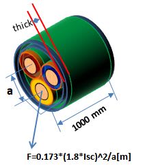
If we shall take for 3*240 mm^2 [copper, XLPE, 0.6/1 kV] and 0.4 sec maximum [as per EN 50522 Fig.4 for 300 V] then Ith[rms] will be 52.2 kA. [If we take 1.8*sqrt(2)*52.2=132.9 kA as current peak value then the maximum force is Fp=sqrt(3)/20*Ip^2/a[m]=65370 N.[The insulated core is 23.4 mm diameter and the overall sheath thickness is 2.9 mm.].
The effort area it is 2*2.9*1000=5800 mm^2/m. Then the tensile effort will be 65370/2/2.9/1000=11.3 N/mm^2. If the minimum tensile strength it is 12.7 N/mm^2 for P.V.C. then the safe factor it is only 12.7/11.3=12.4%
Calculating in the same way for 3*50 mm^2 [insulated core 11.1 mm sheath thick 1.9 mm]
and for 0.4 sec Isc=11.2 kA and Ipeak=28.5 kA then the tensile effort will be only 0.8 N/mm^2
which is only 1/16 of minimum for P.V.C.

Peak_current_force_xf0g6j.jpg
 
Status
Not open for further replies.

Part and Inventory Search

Sponsor