Hello,
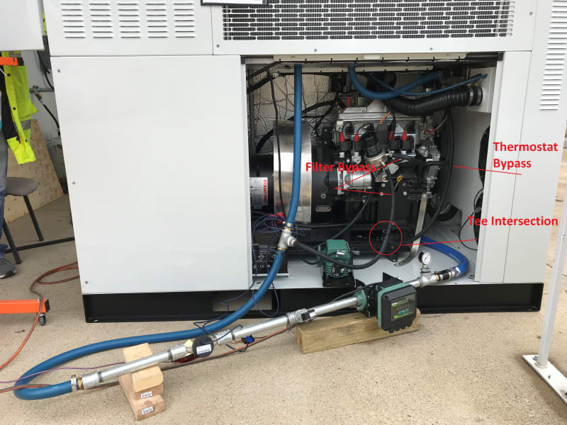
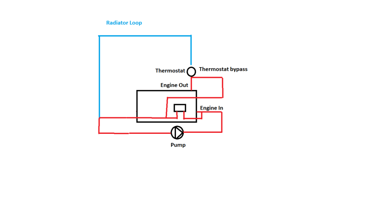
I posted this in another section of the forum and was advised it may be better suited here. I have limited practical experience with pumps and fluid flow systems so please bear with me. I work for a start up company with limited resources/experience and I am trying to determine pressure head in our system. Please reference the picture of our test system set up below (albeit a bit ugly) as well as a crude simplified flow diagram that I have drawn. I am particularly interested in the fluid path that is taken before the thermostat is open at operating temp (shown in red in the flow diagram). The blue hoses you see are 1" and 1 1/4" and flow to the engine and up into a radiator cooling loop. We can ignore the radiator cooling loop at this time because I am just curious about the flow before the thermostat opens. The black 1/2" ID hoses form the bypass system. One bypass originates at the engine inlet and flows through a filter housing. The other is the thermostat bypass and intersects the filter bypass at a tee shown circled in the image below. You can see in the picture that I have integrated a flow meter and pressure gauges at the inlet and outlet of the pump. The readings that I am getting are about 30 ft of head at 4.8 GPM. I have no real reference for if this seems reasonable but perhaps considering there are several hose/pipe size reductions, the biggest being going from 1-1/4" to 1/2", 90 degree turns, tee's, flow meter including size reduction from 1" pipe to 3/4" meter couplings, maybe this is possible? When the thermostat opens up the flow rises to about 6 GPM and 25 ft head after stabilization as fluid travels through the radiator loop. I hope this makes sense, please feel free to ask any additional questions. Appreciate any insight anyone can offer. Thanks, Eric
I posted this in another section of the forum and was advised it may be better suited here. I have limited practical experience with pumps and fluid flow systems so please bear with me. I work for a start up company with limited resources/experience and I am trying to determine pressure head in our system. Please reference the picture of our test system set up below (albeit a bit ugly) as well as a crude simplified flow diagram that I have drawn. I am particularly interested in the fluid path that is taken before the thermostat is open at operating temp (shown in red in the flow diagram). The blue hoses you see are 1" and 1 1/4" and flow to the engine and up into a radiator cooling loop. We can ignore the radiator cooling loop at this time because I am just curious about the flow before the thermostat opens. The black 1/2" ID hoses form the bypass system. One bypass originates at the engine inlet and flows through a filter housing. The other is the thermostat bypass and intersects the filter bypass at a tee shown circled in the image below. You can see in the picture that I have integrated a flow meter and pressure gauges at the inlet and outlet of the pump. The readings that I am getting are about 30 ft of head at 4.8 GPM. I have no real reference for if this seems reasonable but perhaps considering there are several hose/pipe size reductions, the biggest being going from 1-1/4" to 1/2", 90 degree turns, tee's, flow meter including size reduction from 1" pipe to 3/4" meter couplings, maybe this is possible? When the thermostat opens up the flow rises to about 6 GPM and 25 ft head after stabilization as fluid travels through the radiator loop. I hope this makes sense, please feel free to ask any additional questions. Appreciate any insight anyone can offer. Thanks, Eric