Continue to Site

Eng-Tips is the largest engineering community on the Internet

Intelligent Work Forums for Engineering Professionals

  • Congratulations The Obturator on being selected by the Eng-Tips community for having the most helpful posts in the forums last week. Way to Go!

Double Busbar Scheme Question 1

Status
Not open for further replies.

neduetpk

Electrical
Oct 23, 2015
4
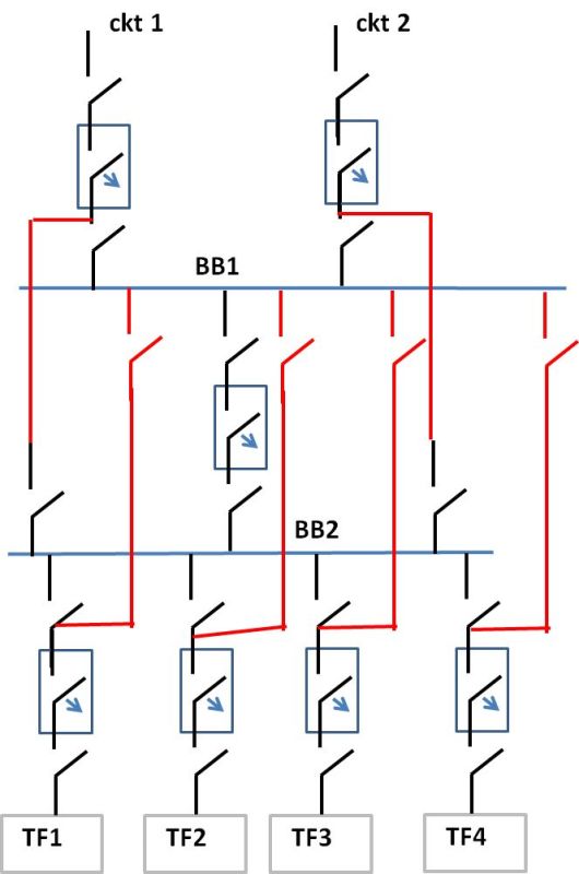
now my question is this system both busbars energized all the time. what is the meaning of main BB and transfer BB and what is the purpose of bus coupler is it always put couple both buses all the time or its open in normal condition ?

thanks

scheme design attached

2ufd54k.jpg
 
Replies continue below

Recommended for you

Not only do I not see any circuit breakers, I can't tell what's connected to what...in my view, a great deal of information is missing, so much so that providing an intelligent response is well-nigh impossible.

Your profile says nothing about you; are you a student? If so, what year? Or are you a graduate and looking for a job? Or are you employed in an entry-level position and trying to orient yourself to your surroundings?
Have you no colleagues or peers to answer your questions?

As others have stated: "More information yields better answers!"

CR

"As iron sharpens iron, so one person sharpens another." [Proverbs 27:17, NIV]
 
Hi neduetpk
Let me have ago We have used this system on Mining Main Consumer substations, we called the rear bars "Hospital" bars "Double Bus Switchgear" where we would have Three or four Identical designed 20MVA 88 /11kV Dyn11 transformers connected either front or rear very useful for switching loads and taking Transformers out of service hence the need for Bus bar "couplers".
Shame guys give the guy some help.
Paddy
 
No shame should be given. I've seen many forms of schematics from all over the world. I had and still have no clue how to interprate it.
 
The drawing is simply terrible. There is just no way to sugar coat how bad it is. But, it appears to be a main-tie-main scheme where each load can be powered from either bus.

I can't answer the questions because there is no "main BB", "transfer BB" or bus couplers on the drawing.
 
I remember a scheme that may have been similar if we make some allowances for the schematic quality.
It was in an underground substation feeding part of the city core of a major city.
Rather than local transformers, the feeds were outgoing feeders to remote transformers.
The second bus was for maintenance.
Some assumptions;
BB1 Service Bus.
BB2 Maintenance Bus.
DS Dis-connector. (breaker or non-automatic switch.)
In the scheme that I remember, each outgoing feeder had a normal service breaker connecting it to the service bus, BB1. (Small DS.)
Each outgoing feeder had a non-automatic switch connecting it to BB2. (Small DS)
BB1 bus could be connected to BB2 bus by the maintenance breaker (Large DS)
Each normal service breaker (Small DS) had the normal protection relays and the trip signal from each protection package could be switched to trip the maintenance breaker.
In the event that a service breaker needed to be repaired or examined (for example after clearing a fault):
1> The trip signal would be paralleled with the maintenance breaker. (Large DS)
2> The switch to the maintenance breaker would be closed. (Small DS)
3> The transformer or feeder breaker would be opened. (Small DS)
Now the outgoing load is supplied by the maintenance breaker, but with the same protection package.
The service breaker may now be removed for inspection and/or repair.
The load has not been taken out of service and the protection has not been compromised.
I may be completely wrong in this application, but then again I may be right.

Bill
--------------------
"Why not the best?"
Jimmy Carter
 
In my opinion,the actual one-line diagram has to be as attached:
BB_132_KV_IMPROVED_ONE_LINE_DIAGRAM_mhlbou.jpg
 
thanks for the drawing.


crshears said:
i am entry-level position employee and yes trying to understand switch yard

my drawing is this. and my questions are this system both busbars energized all the time. what is the meaning of main BB and transfer BB and what is the purpose of bus coupler is it always put couple both buses all the time or its open in normal condition ?

2eeeao5.jpg


thanks a lot guys
 
Let’s say BB1 is the main busbar and BB2 is the transfer bar.
With main bar all the line and transformers are connected , usually . The transfer bar could be not energized usually. However, if there is a trouble with the first one you may close the couple circuit breaker and to supply one or all transformers from the transfer bar. Closing then the incoming line disconnector to the transfer bar and open the disconnector from the main busbar you may de-energize the main bar for repair or test.
 
In such configuration a both BB are Main.
Double bus or single bus with transfer bus is another configuration.
Bus coupler is used for transfer bay from one bus to other.

procedure is simple: close DS1 and DS2 of coupler, close CB of coupler.
Close DS2 os some bay, open DS1 of this bay, open CB coupler
 
Isnt this scheme (double buss single breaker) employed so if a breaker failure took place only 1/2 the lines and transformers would be de-enrigized?
 
7anoter4 said:
The transfer bar could be not energized usually
If the transfer bus is normally de-energized, you may find it unavailable when needed. Best to keep it energized but unloaded, so that any faults are discovered near the time of occurrence.
 
Status
Not open for further replies.

Part and Inventory Search

Sponsor